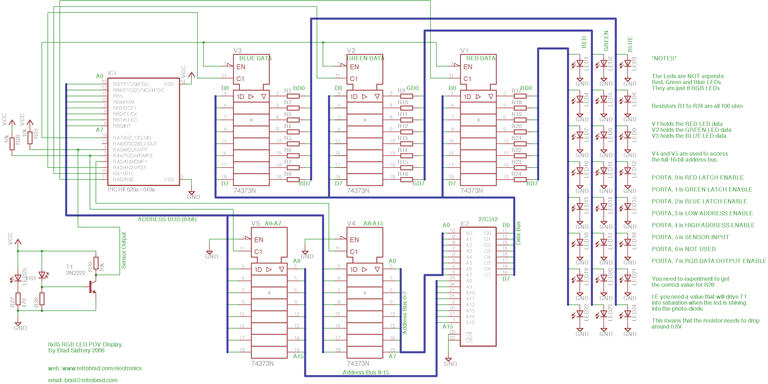
The drawing process is really quite simple. The pic microcontroller puts 00000000 00000000 on the eeproms address bus (selects the first address) This byte of info (at that address) is now placed on the data bus and all RED GREEN AND BLUE 74373’s are connected to this data bus. We only want red to grab this first byte of data so the microcontroller enables the red latch then closes it which means we have saved that byte to the RED 74373. Then it increments to the next address an latches that byte to the GREEN 74373 and then we increment to the next address then latch it to the BLUE 74373.
Now that all 74373’s have their data - the microcontroller then enables their outputs which sends the data to the LEDS. So we have just displayed one column (of the 85 per frame) So these leds will stay on for just a fraction of a second then turn off and we repeat the process to draw the next column and keep doing this untill one whole frame is drawn (85 columns).
The key thing to remember here is that it always follows the sequence RED, then GREEN then BLUE.
Lets do some math - if it takes 1 byte of red, 1 byte of green and one byte of blue per column then it is 3 bytes or 24 bits per column - then if there are 85 columns per frame that means that there is 3×85 = 255 bytes per frame or 2040bits per frame. If we use a 27E512 EEPROM then this holds 64kbytes which means 64k / 255 = approximately 255 frames. This means we can cycle through frames to make animations! See the next videos for examples of this.
I have also added a sensor to it so it knows when to start drawing each frame (without the sensor the project is subject to drifting (i.e the display does not stay in the one place no matter how much you try to adjust the motor speed) You can see the difference between having a sensor and not having a sensor in my youtube videos. The RETROBRAD logo has no sensor and therefor keeps drifting, but the other videos do have the sensor and therefor remain in the one position. The sensor is made of an IR LED shining straight into a photo diode. When there is nothing interrupting the signal, the photo diode has max current and therefor drops max voltage across it’s resistor. This means that the npn transistor connected to it will saturate and therefor send a logic 0 to the microcontroller. But when the sensor passes the nail (so it interupts the light beam, the photo-diodes current decreases causes the voltage of the resistor to decrease and therefor turns off the transistor - this then sends out a logic 1 to the microcontroller to say that we’ve passed the check-point and to start drwaing the next frame - See the schematic for more information.
I am also working on using brushes to transfer +5v dc to the circuit which means i wont have to use batteries.
(See my 32×64 POV display to see how i managed to transfer power to the spinning board)
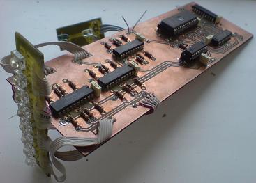
I have been asked by a number of people - "How do you mount the board to the motor?" we'll here is the answer for you all!
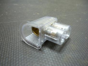
I bought a pack of electrical termination screw connectors from a hardware store which cost just a few dollars. Here is what one looks like straight out of the packet:
And here it is again, taken out of it's plastic shell:
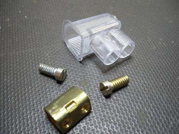
I used a file to rough up one end of the shaft. Then I soldered this to the underside of my circuit board so that it was secure. then i screwed the two grub screws back in, and then you can put the motor shaft inside this metal casing and then tighten the two grub screws to hold it in place. And that's it! that's how you mount your circuit board to the motor.
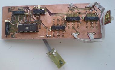
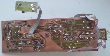
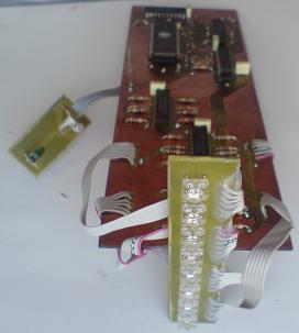
Unfortunately I lost my original PCB layout files when I upgraded my laptop. BUT Dai Omie has been very kind to share his own version of the 8x85 PCB layout files. and you can download all you need to know in this archive:
And here are some images of his completed project. Very professional!
Please click the thumbnail to view the full-size schematic.
Alternatively, you can download the schematic diagram in eagle CAD format:
8×85_led_pov_display_schematic
You can download the assembly source code here: *NOTE THIS HAS BEEN UPDATED AS OF 01 OCT 2008*