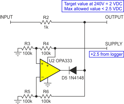
This circuit was born from an application that required an input signal to be precisely clamped to less than 2.5 V, while operating on a 2.5 V supply (actually a reference) with a maximum output of 4 mA. Since the signal’s dynamic range is from 0 to 2.5 V, clamping it with a simple diode or Zener would eat up too much of the signal’s range. In addition, the signal requires a clamping voltage that is more precisely regulated than either device can provide.
This solution (see Figure 1) is based on a rail-to-rail op amp capable of operating at 2.5 V but, even then, operating the input and output nodes of the amplifier near the center of its 0 to 2.5 V range provides the best linearity.
 |
||
| Figure 1. | Clamp circuit to precision clamp a 2.5 Volt output while operating on a 2.5 Volt power supply. |
|
To achieve this, the reference voltage is halved via the divider R3/R4 and applied to the non-inverting input. The sensed voltage is also halved via the divider formed by R5/R6 and applied to the inverting input.
Lastly, D5 in the output of the amplifier only allows the amplifier to sink voltage from the OUTPUT node if the level attempts to exceed 2.5 V. The use of four identical-value resistors makes achieving accuracy easy because of the ready availability of precision ratio-matched resistor networks.
R2 acts as a series resistance for the clamp action of the amplifier output. The value of R2 can vary widely depending on the application but consider that the OPA333 op amp used here (U2) is specified for a 5 mA output current maximum.
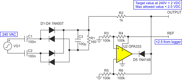
An example of the implementation of this clamp is shown with the AC voltage measurement circuit it was originally created for (Figure 2).
 |
||
| Figure 2. | Clamping circuit shown with the AC voltage measurement circuit. | |
The AC voltage measurement circuit feeds a logger that has a maximum input voltage rating of 2.5 V. The logger also provides a 2.5 V reference output. The challenge is that the logger input must never exceed 2.5 V. This level is clamped by the circuit formed around the OPA333 op amp, U2.
 |
||
| Figure 3. | Simulation of AC input 5000 V transient at the input of the AC measurement circuit of Figure 2. | |
A capacitive attenuator and rectifier network is used to measure a 240 VAC line where the intended output will be at 2 VDC with 240 VAC input. Figure 3 depicts a simulation of a 5 kV transient at the AC input.
Conclusions
The circuit’s simplicity, performance and low cost of implementation which made it more than satisfactory for my application should make it a good solution in other data acquisition and sensing applications which need fast, precise, and affordable overvoltage protection.
