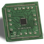
Plug-in module Microchip MA330026
The dsPIC33FJ16MC102 and PIC24FJ16MC102 plug-in modules (PIMs) (Part No.
Detailed Description
MA330026 and MA240026) are designed to demonstrate the capabilities of the dsPIC33FJ16MC102 and PIC24FJ16MC102 motor control devices using the dsPICDEM MCLV Development Board (DM330021) or dsPICDEM MCHV Development Board (DM330023).
The dsPIC33FJ16MC102 device is an ultra low cost high-performance 16-bit digital signal controller within a small 28-pin 6x6 mm QFN package. The PIC24FJ16MC102 device offers the same functionality as the dsPIC33FJ16MC102, with the exception of DSP capabilities.
Both devices are equipped with Peripheral Pin Select (PPS), which allows many of the digital peripherals to be remapped to use any number of pins on the device.
dsPIC33FJ16MC102 Features
- CPU:
- Up to 16 MIPS operation (3.0 - 3.6V)
- Modified Harvard architecture
- 16-bit-wide data path
- 24-bit-wide instructions
- 16 x 16 integer multiply operations
- 32/16 and 16/16 integer divide operation
- Two 40-bit accumulators with rounding and saturation options
- Additional flexible and powerful addressing modes: - Modulo - Bit-reversed
- Single-cycle multiply and accumulate: - Accumulator write back for DSP operations - Dual data fetch
- Shifts for up to 40-bit data
- 16 x 16 fractional multiply/divide operations
- 32/16 and 16/16 integer divide operation
- On-Chip Flash and SRAM:
- Flash program memory (16 Kbytes)
- Data SRAM (1 Kbyte)
- Security for program Flash
- Motor Control PWM:
- 6-channel 16-bit Motor Control PWM:
- Three duty cycle generators
- Independent or Complementary mode
- Programmable dead time and output polarity
- Edge-aligned or center-aligned
- 6-channel 16-bit Motor Control PWM:
- Analog Peripherals:
- 10-bit, 1.1 Msps Analog-to-Digital Converter (ADC): - Two and four simultaneous samples - Up to six input channels with auto-scanning
- Three Analog Comparators with programmable input/output configuration
- Up to four inputs per Comparator
- Charge Time Measurement Unit (CTMU): - Supports capacitive touch sensing for touch screens and capacitive switches (mTouch)
- Timers/Capture/Compare/PWM:
- Timer/Counters, up to three 16-bit timers: - Can pair up to make one 32-bit timer
- Input Capture (up to three channels) - Capture on up, down, or both edges - 16-bit capture input functions
- Output Compare (up to two channels) - Single or Dual 16-bit Compare mode
- Hardware Real-Time Clock and Calendar (RTCC)
- Communication Modules:
- 4-wire SPI
- I2C
- UART
- System Management:
- Flexible clock options
- High-accuracy internal FRC
- Power-on Reset (POR)
- Power-up Timer (PWRT)
- Brown-out Reset (BOR) Power Management:
- Single supply on-chip voltage regulator
- Switch between clock sources in real time
- Idle, Sleep, and Doze modes with fast wake-up
- Packaging:
- 28-pin SPDIP/SOIC/SSOP/QFN
- 28-pin QFN: 6×6 mm
- 36-pin TLA: 5×5 mm
The PIMs take advantage of PPS by using zero ohm resistors to connect the I/O to the Development Board. Simply removing the zero ohm resistors and using the test points associated with each I/O pin (i.e., RP0, RP1, etc.), allows the designer to reroute the pin to any of the available pins on the Development Board. This capability enables easier and faster design times.
