Dual Motor Control Plug-in-Module Microchip MA330027
The dsPIC33EP512MU810 Dual Motor Control Plug-In Module (PIM) is designed to facilitate the development of Motor Control applications using two motors and one Digital Signal Controller (DSC).
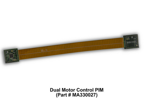
Detailed Description
Two Microchip dsPICDEM motor control development boards can be used with this PIM to control 3-phase BLDC, PMSM, ACIM or 2-phase stepper motors. A flexible cable connects the two boards together and routes all signals to the appropriate pins on the DSC. The configuration of the cable and signals was carefully chosen to support a wide range of dual motor configuration application notes written for the dsPICDEM MCLV, MCHV, and MCSM Development Boards.
dsPIC33EP512MU810 Features:
- CPU
- Up to 60 MIPS Operation (at 3.0V-3.6V)
- Modified Harvard Architecture
- C Compiler Optimized Instruction Set
- 16-bit Wide Data Path
- 24-bit Wide Instructions
- 16x16 Integer Multiply Operations
- 32/16 and 16/16 Integer Divide Operations
- 11 Additional Instructions
- Two 40-bit Accumulators with Rounding and Saturation Options
- Flexible and Powerful Addressing modes
- Single-Cycle Multiply and Accumulate
- Single-Cycle shifts for up to 40-bit Data
- 16x16 Fractional Multiply/Divide Operations
- On-Chip Flash and SRAM
- Flash Program Memory (up to 512 Kbytes)
- Flash Auxiliary Memory (up to 24 Kbytes): - Can be used as Bootloader space or for EEPROM emulation without stalling the CPU
- Data SRAM (up to 52 Kbytes)
- Motor Control Peripherals
- Motor Control PWM:
- Two master time base modules can control dual 3-phase motors simultaneously
- Up to seven PWM generators
- Two PWM outputs per PWM generator
- Quadrature Encoder Interface (QEI): - 32-bit position counter - 32-bit Index pulse counter
- Motor Control PWM:
- Direct Memory Access (DMA)
- 15-Channel Hardware DMA
- Up to 4 Kbytes Dual Ported DMA Buffer Area (DPSRAM) to store data transferred via DMA
- Most Peripherals Support DMA
- Analog Peripherals
- 10-bit, 1.1 Msps or 12-bit, 500 Ksps Conversion:
- Two and four simultaneous samples (10-bit mode)
- Up to 32 input channels with auto-scanning Three Analog Comparators with Programmable Input/Output Configuration
- 10-bit, 1.1 Msps or 12-bit, 500 Ksps Conversion:
- Timers/Capture/Compare/PWM
- 41 user-definable Timer/Counters
- up to 9 16-bit Timers/Counters
- 16 Input Capture
- 16 Output Compare/PWM
- Hardware Real-Time Clock and Calendar
- 41 user-definable Timer/Counters
- Communication Modules
- USB On-The-Go (OTG)
- USB module can use any RAM location on the device as USB endpoint buffers
- 4-wire SPI (up to four modules)
- I2C (up to two modules)
- UART (up to four modules)
- Enhanced CAN (ECAN) 2.0B active (up to two modules)
- Parallel Master Slave Port (PMP/EPSP)
- Programmable Cyclic Redundancy Check (CRC) Data Converter Interface (DCI) Module
- Codec Interface
- Supports I2S and AC’97 Protocols
- Up to 16-bit Data Words, up to 16 Words per Frame
- System Management
- Flexible Clock Options
- Programmable Power-up Timer
- Oscillator Start-up Timer
- Watchdog Timer with its own RC Oscillator Power Management:
- On-chip 1.8V Voltage Regulator
- Switch between Clock Sources in Real Time
- Idle, Sleep, and Doze modes with Fast Wake-up
- Packaging:
- 64-pin QFN (9x9x0.9 mm)
- 64-pin TQFP (10x10x1 mm)
- 100-pin TQFP (12x12x1 mm)
- 100-pin TQFP (14x14x1 mm)
- 121-pin BGA (10x10x1.2 mm)
- 144-pin LQFP (20x20x1.4 mm)
- 144-pin TQFP (16x16x1 mm)
