Short-Circuit Indicators: What They Are and How They Work
Short-circuit indicators are compact devices fitted on power distribution networks to detect and show where an electrical short or earth (ground) fault has occurred. They don’t clear the fault — instead they act like early-warning beacons and location markers for crews, making it far quicker to find a faulted section of cable or equipment and begin repairs.
How they work
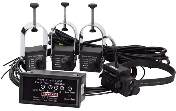
In practice these indicators combine a sensing element with a clear visual or electronic flag. The sensing element monitors current or magnetic field around a conductor and looks for the signature of a short (very high local fault current or unbalanced current to earth). When that signature appears the device sets an indicator (mechanical flag, LED, or a digital status) that stays latched until a technician resets it. This behavior lets crew members patrol lines or inspect substations and immediately know where the fault traveled to — dramatically reducing the search area and repair time.
Physical design and mounting
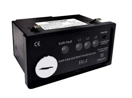
Physically, short-circuit indicators are built for the field. Typical units have a rugged, weatherproof housing and one of several mounting styles: clamp-on sensors that wrap around a cable, through-core forms for insulated conductors, or bolt-on modules for switchgear and transformer terminations. The visible indicator can be a bright mechanical flag that flips to a conspicuous position, an LED array that lights up, or a digital output that reports status to a supervisory system. Many models are compact enough to be installed on underground cable terminations, overhead lines, and inside substations without special tools.

Advanced features and integration
Beyond the basic “flag-and-latch” function, modern devices often include features that make them part of a broader fault-management workflow: multi-phase sensing to distinguish which phases are involved, immunity settings to avoid false trips during switching or inrush currents, and communications or SCADA outputs so indicators can be read remotely. These enhancements allow operators to prioritize crews, feed data into outage-management systems, and reduce unnecessary patrols.
Choosing the right unit
If you’re comparing hardware or planning upgrades, look for specifications that match your network needs: detection thresholds (sensitivity to phase-to-phase vs. earth faults), mounting options that suit your cable insulation and terminations, environmental ratings (temperature, UV and moisture resistance), and any available digital interfaces for remote monitoring. Products marketed as a short circuit sensor or short circuit indicator typically list these parameters so you can match a unit to underground or overhead installations and to the fault currents your network can produce.

Benefits for power networks
For operators working with cable-fed distribution and substation assets, circuit indicator power lines solutions are especially valuable because they speed restoration in dense urban networks and critical infrastructure sites. When specifying equipment, check whether the device supports multi-phase systems, SCADA integration, and the physical layouts encountered on your lines — these are the features that turn a simple visual flag into a genuinely time-saving troubleshooting tool.

Models and datasheets
Examples of common model lines (for reference when requesting datasheets or comparing options) include compact field-mount units and “pro” versions with expanded sensing or communications capabilities; look at model pages and the technical catalogue to match form factor and functionality to your route and fault-management process.
If you want to review a supplier’s specific product list and datasheets while you plan, you can learn more about a short circuit indicator, a short circuit sensor, and circuit indicator power lines from product pages that collect models, technical details, and catalogue downloads.