Alfredo Medina & Mohamed Ismail
EDN
Power accumulators enable a variety of applications that require average power measurement. One example is real-time measurement of switching converter efficiency, which permits converter efficiency evaluation over time and varying operating conditions. Expanding this idea to multiple rails allows the monitoring of power management integrated circuits (PMICs) in battery-powered, high-density systems. In addition, power accumulation facilitates rapid prototyping by monitoring various system rails during development. The logged data can be used as feedback to a designer for continuous improvement of system design. These are just a few applications that demonstrate the value of using a power accumulator to provide critical, real-time power measurements.
Introduction
In an electrical system, measuring the power consumed by critical system rails provides telemetry of vital system functions. By looking at real-time power consumption, a system can perform dynamic optimization to prolong battery life. Power monitors sample the voltage and current of a rail and provide an instantaneous power measurement. While power monitors are often used in systems that constantly monitor the peak power of a system rail, greater computation is required if average power is needed. To obtain an average power measurement, the instantaneous power readings must be accumulated over a specified time interval. Power monitors require additional processing to accumulate and compute average power, which places a limitation on systems with limited processing capacity. For this reason, traditional power monitors are not well suited for average power measurements. Power accumulators are like power monitors, but have the accumulation feature integrated to provide a system host with average power readings. The reduction in processor overhead makes power accumulators an ideal solution for average power monitoring in systems with limited processing capacity.
Operation
Power accumulators measure voltage and current samples, multiply them to get a power reading, and add multiple readings to get an accumulated power value. Accumulated power and sample count information is stored on-chip.
As an example, see the MAX34407 block diagram shown in Figure 1. MAX34407 automatically collects current and voltage samples from four channels using a multiplexer, current-sense amplifier, and 12-bit ADC. The voltage and current samples are multiplied on-chip to obtain a 28-bit power value for each sample pair. The power values are added and stored in a 48-bit register, and the count of instantaneous power samples accumulated is stored in a 24-bit register. The use of an automatic sequencer and integrated oscillator make the MAX34407 fully autonomous, as it does not require an external sample clock.
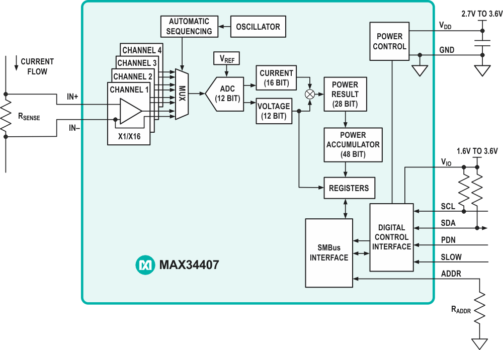 |
||
| Figure 1. | MAX34407 Power Accumulator Block Diagram. | |
Upon an I2C/SMBus command from the host, the device transfers the accumulated power samples and count to a set of registers available to the host. This transfer occurs without missing a sample and allows the host to retrieve data at any time interval. In normal mode, the MAX34407 samples at a rate of 1,024 sps. Since the accumulation depth is 48 bits while individual samples are 28 bits, 220 samples can be stored before the host controller needs to read back the data:

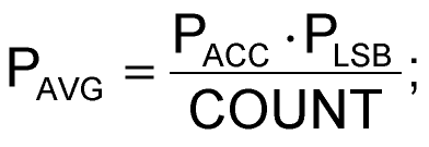
Once the host receives power accumulation and count data, a basic computation results in average load power. This process relieves the burden of accumulating power data and liberates the host processor to manage more important tasks. The power accumulation data is converted by the host processor using a scaling factor. The scaling factor is determined using the following constants and equations, where PACC is the accumulated power value and COUNT is the total number of power samples:
MAX34407-specific constants:
- Voltage-sense full scale
VFS = 16 V - Current-sense full scale
VSENSE = 100 mV - Power-accumulated word length:
28 bits
Scaling factor:
- Full-scale current
- Power-scale correction
- Least significant power bit
- Average power calculation:
The above is an example of converting the accumulated ADC count to average power using MAX34407. Power accumulators will range in features and operation; thus, it is important to consider the specific operation of each power accumulator.
Single IC Efficiency Measurement
By using a power accumulator with multiple rails, efficiency measurements can be taken using a single IC. Efficiency is one of the most important specifications in any power converter. Once a design is implemented, the designer or end-user does not have access to real-time converter efficiency measurements, which will vary over time and operating conditions. Component drift, load conditions, and environmental factors like temperature and humidity all impact converter performance over time. Thus, it becomes valuable to provide a method for monitoring a converter’s efficiency in real time.
Since the MAX34407 accumulates power on multiple rails, efficiency can be measured by accumulating power at the input (PIN) and output (POUT) of a converter. The result of these two measurements may be sent to a microprocessor for efficiency computation using the following formula:
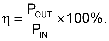
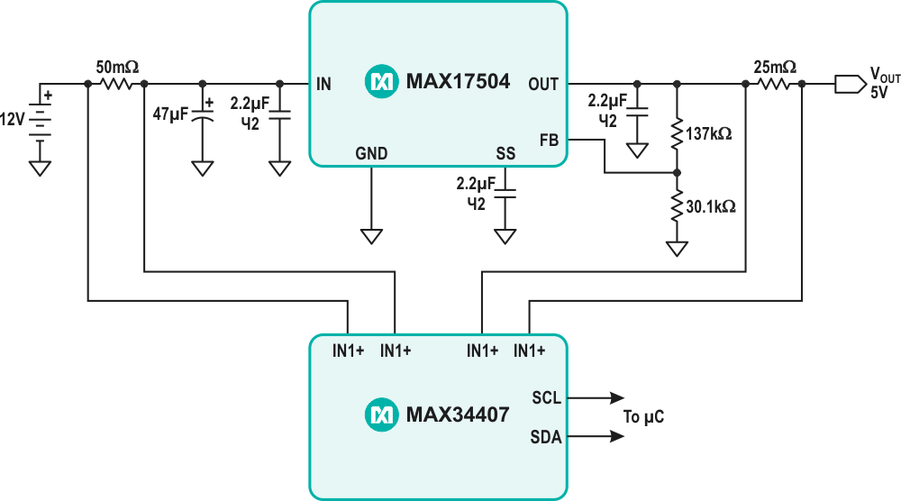
Figure 2 demonstrates a typical circuit for measuring efficiency of the MAXM17504 step-down converter using the MAX34407 power accumulator. An example application for this circuit is a 12 V solar panel system where the primary converter typically incorporates a maximum power point tracking (MPPT) algorithm. Real-time efficiency measurements provide feedback of MPPT algorithm performance. This allows the system or designer to optimize the MPPT algorithm based on in-circuit measurements. MAXM17504 input voltage range is 12 V ±10%, which fits into MAX34407 common-mode voltage range of +2.7 V to +15 V. The full-scale range of the current-sense amplifier is 100 mV, so a 50 mΩ resistor was used on the input for 2 A maximum input current and a 25 mΩ resistor was used on the output for 4 A maximum output current.
 |
||
| Figure 2. | Efficiency Measurement Application Circuit. | |
 |
||
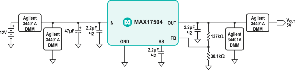
| Figure 3. | Efficiency Measurement Circuit using 4 DMMs. | |
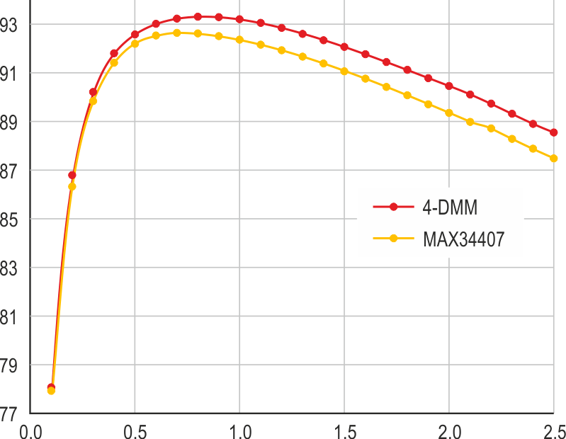
In Figure 3, the efficiency measurement circuit using 4-DMMs demonstrates an alternative method for measuring efficiency using four benchtop digital multi-meters (DMM). The 4-DMM method measures input current, output current, input voltage, and output voltage to obtain a highly accurate efficiency measurement. The 4-DMM method is used as a baseline measurement for comparison with the efficiency measurement obtained from the power accumulator IC. An efficiency comparison between MAX34407 and the four DMM efficiency measurement methods is shown in Figure 4.
 |
||
| Figure 4. | MAX34407 Efficiency Measurement vs. 4-DMM Method. | |
 |
||
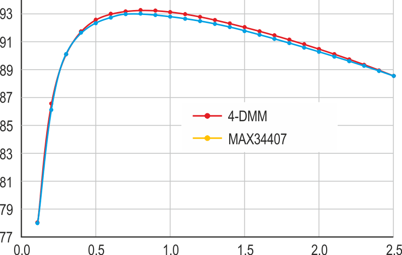
| Figure 5. | MAX34407 Compensated Efficiency Measurement vs. 4-DMM Method. |
|
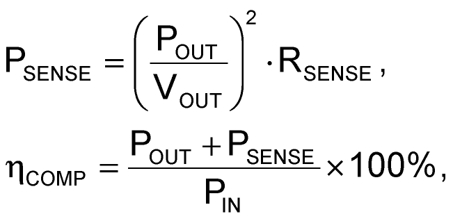
The notable offset in the two methods is attributed to the power dissipated in the output current sense resistor. This value is included in the input power measurement but not in the output power measurement, since MAX34407 measures the common-mode load voltage from the lower voltage terminal of the sense resistor. Measured output power may be compensated by adding the calculated sense resistor power dissipation, which yields the total output power. The equations used to compensate the efficiency measurements are shown below, where Pout and VOUT are measured by MAX34407 and RSENSE is a known value. The results of the compensated efficiency measurement are shown in Figure 5.
The results of Figure 5 demonstrate a maximum difference of –0.5% between the 4-DMM and MAX34407 efficiency measurements. This shows the MAX34407 can be used to accurately measure in-system efficiency of a switching converter with proper output power compensation. It is important to note that the compensation technique works best for converters with a ripple voltage of 1% or less.
