The analog priority amplifier shown in Figure 1 was originally conceived as part of a multiple output power supply where the voltage regulation was based on the level of the highest channel. Another application was an engine control system with an electronic throttle control where it was desired to have the engine respond to the highest command of several inputs.
 |
|
| Figure 1. | Input Priority Amplifier provides an output from the most positive of four inputs. This circuit responds to positive inputs, but by reversing the diodes and re-configuring the power supplies, it can respond to negative inputs. |
In the circuit, the amplifier with the most positive output controls the negative feedback path via the forward biased diode in the amplifier output. It forms a simple unity gain path via R1 or R2, R3 or R4, depending on which channel is the most positive, into the inverting input of the amplifier. The diode between the inverting input and the output is reversed biased on the amplifier with the largest input resulting in the circuit operating as an amplifier with unity gain from its input to the overall output.
The outputs of the amplifiers with weaker inputs are forced to go negative from the output value until their feedback diode, D2 (or diode for any corresponding amplifier), is forward biased so that the amplifiers remain in a local closed loop condition. The 10k resistors, such as R1, allow the weaker amplifiers to operate as unity gain buffers by forming a local feedback network. Figure 2 depicts simulation results using all four channels.
 |
|
| Figure 2. | Simulation plot of the output of the 4-channel priority amplifier. |
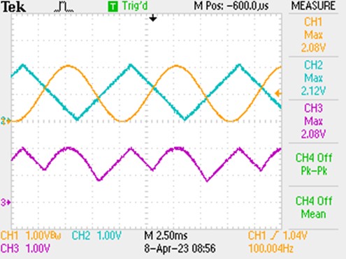
Dissimilar input signals are applied to dramatize the effect when two different waveforms compete for the highest amplitude at various intervals. Figure 3 shows actual oscilloscope traces of a two-channel version of the amplifier with the output on Channel 3 (note that the zero for Channel 3 is down lower on the scope screen than the zero for Channel 1 and 2).
 |
|
| Figure 3. | Scope plot of a two-channel version of the priority amplifier. Channels 1 and 2 are input signals, Channel 3 is the output. (Note that the scope zero for Channel 3 is down lower on the scope screen than the scope zero for Channel 1 and 2.) |
While this circuit is configured to operate on positive voltages, adapting it to negative voltages merely involves reversing the diode connections and setting up the power supply voltages appropriately.
The circuit shown uses a Microchip MCP6V51/2/4 op amp, however, a wide choice of op amps could be candidates. Considerations in the choice include:
- Often most applications will require an op amp that has a common-mode range that includes the negative supply rail of the op amp, which is usually ground. In some cases, an amplifier with rail-to-rail common-mode range may be required.
- It should be obvious that sensor or input signal levels, as well as output signal requirements, determine what the voltage rating of the op amps needs to be.
- Unity gain stability is essential for this circuit. Using it with the output into capacitive loads may require additional compensation to maintain stability.
