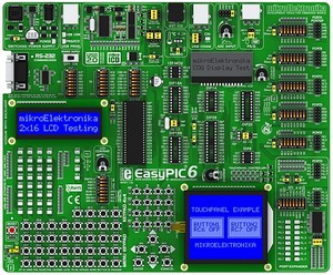
Development system mikroElektronika EASYPIC6
EasyPIC6 is a development system that supports over 120 PIC MCU (8, 14, 18, 20, 28 and 40 pin).
Detailed Description
3 in 1 Development System - Development System + On-Board USB 2.0 programmer + On-Board mikroICD (In-Circuit Debugger): mikroICD is a highly effective tool for Real-Time debugging on a hardware level.
The mikroICD enables you to execute a mikroC, mikroPascal or mikroBasic program on a host PIC microcontroller and view variable values, Special Function Registers (SFR), memory and EEPROM as the program is running. Also there is ultra fast USB 2.0 programmer for fast MCU programming that now supports more PIC microcontrollers.
State-Of-The-Art very fast USB 2.0 programmer on-board with simplified driver installation. The mikroICD is a hardware tool designed for testing and debugging programs on PIC microcontrollers.
EasyPIC6 allows the PIC microcontroller to be interfaced with external circuits to a broad range of the peripheral devices. There is on-board Port Expander (MCP23S17, the 16-bit I/O expander that uses SPI communication). This development Board is ROHS compilant and lead-free. EasyPIC6 contains on-board Touch Screen controller with connector for easier Touch Panel connecting.
Examples that comes with this development system will show you how to connect the PIC microcontroller easily with other peripheral components or devices when developing your prototype device. Each example contains detailed description and comments of the program.
Features:
- RS-232 communication with PC or another microcontroller is available via DB9 connector.
- System can be easily configured via clearly marked DIP switches. Each DIP switch configures part of system.
- Digital thermometer DS1820 for measuring temperature from -55°C to 125°C can be connected to system via socket.
- Support for MCU's in DIP8, DIP14, DIP18, DIP20, DIP28 and DIP40 socket. Board is delivered with PIC16F887.
- 2 potentiometers are available for testing multiple AD conversion. Input can be configured via jumpers.
- Power Supply select - USB or external, just by moving jumper. Also there is a switch for turning on/off system.
- 4 seven-segment digits in multiplex mode
- 2x16 Character COG Display is available on-board for displaying text messages. Display is connected via SPI.
- All pins are connected to IDC10 connectors for further expansion. All pins of these connectors are marked on-board.
- There are 36 LED (Light Emmiting Diodes) for displaying states of all pins on the MCU at the same time.
- There are jumpers on-board that are used for Pull up or Pull down port defining. These jumers are available for all pins.
- There are 36 buttons for program developing needs. These buttons are connected to all microcontrollers pins.
- DIP switch is available on-board for easy separating port pins from Pull up or Pull down resistors.
- There is very fast USB 2.0 programmer with mikroICD on-board. There is no need for connecting external programmer.
- LCD display can be easily connected via connector that can be found on-board. This connector is connected to MCU pins.
- There is LCD Contrast Potentiometer on-board that is used for adjusting LCD Contrast very fast and easy.
- Touch Screen can be connected to the board via Touch screen connector. There is also a Touch Screen controller.
- External power supply can be DC or AC. There is a jumper on-board that is used for selecting external power supply.
- Crystal can be replaced by another one. There are jumpers for configuring pins as oscillator inputs or regular I/O pins.
- Graphic LCD 128×64 can be easily connected via connector that can be found on-board and is connected to MCU pins.
- All pins are marked on the back of the board. These marks describe connections, modes, and some other useful notes.
- Choose voltage level to be applied when a button is pressed (GND or +5V) via on-board jumper that is used for this selection.
- USB communication connector for MCU's with USB facilities. Connect your microcontroller with PC via USB interface.
- There is a reset circuit on-board that is connected to the MCLR Pin of the microcontroller.
- PS2 connector enables direct connection between development board and PS/2 device such as keyboard or mouse.
- On-board 4x4 Keypad allows efficient entry of numerical data as well as other characters.
- Menu Keypad enables easy and fast menu browsing for your prototype device.
- There is Port Expander on-board if there is need for more inputs or outputs.
Package contains:
- EasyPIC6 development system.
- USB cable.
- CD with software, drivers and examples in C, BASIC and Pascal.
- Printed Documentation that includes: EasyPIC6 Manual, EasyPIC6 Schematic Diagram, PICFlash with mikroICD Manual, mikroICD Manual and Quick Guide for Installing USB Drivers).
- The Box is very resistant to shock and transport damage.
Schematic diagram EasyPIC6 development board
Other Names:
MEEASYPIC6, EASYPIC6, ME EASYPIC6, EASYPIC6, ME-EASYPIC6 EASYPIC6, ME-EASYPIC6 EASYPIC6
