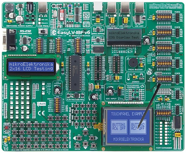
mikroElektronika announces the release of EasyLV-18F v6 Development System, which allows users to develop and design devices using Microchip PIC18J and PIC18K-series microcontrollers. The new system supports 40-, 28- and 20-pin PIC18FxxJxx (PIC18FxxKxx) devices. The board includes features such as: USB 2.0 programmer with mikroICD and many peripheral modules such as: Serial RAM, Serial EEPROM, Serial COG Display, Piezo Speaker etc. Each feature of the board is supported by example written in mikroC, mikroPascal and mikroBasic PRO for PIC compilers. Also, tool comes with the full color printed documentation.
3 in 1 Development System - Development System + On-Board USB 2.0 programmer + On-Board mikroICD (In-Circuit Debugger): mikroICD is a highly effective tool for Real-Time debugging on a hardware level. The mikroICD enables you to execute a mikroC, mikroPascal or mikroBasic program on a host PIC18J or PIC18K microcontroller and view variables values, Special Function Registers (SFR), memory and EEPROM as the program is running. Also there is ultra fast USB 2.0 programmer for fast programming that supports wide range of PIC18J and PIC18K microcontrollers.
Features
- RS-232 communication with PC or microcontroller is available via DB9 connector and MAX232 level converter.
- System can be configured via clearly marked DIP switches. Each DIP switch configures a part of the system.
- On-board Voltage Regulator is used to reduce power supply voltage from 5V to 3.3V.
- Support for microcontrollers in DIP40, DIP28 and DIP20 socket. Board is delivered with PIC18F45K20 device.
- Potentiometer is available for testing multiple AD conversion. Input can be configured via on-board jumper.
- USB or External Power Supply selection is done just by moving jumper. Also there is a switch for turning on/off system.
- External ICD Connector is used for connecting external programmer or debugger. Jumpers are used for pin selection.
- All pins are connected to IDC10 connectors for further expansion. All pins of these connectors are marked on-board.
- There are 35 LED (Light Emmiting Diodes) for displaying states of all pins on the MCU at the same time.
- There are jumpers on-board that are used for Pull up or Pull down port defining. These jumers are available for all pins.
- There are 35 buttons for program developing needs. These buttons are connected to all microcontrollers pins.
- DIP switch is available on-board for easy separating port pins from Pull up or Pull down resistors.
- There is very fast USB 2.0 programmer with mikroICD on-board. There is no need for connecting external programmer.
- LCD display can be easily connected via connector that can be found on-board. This connector is connected to MCU pins.
- There is GLCD Contrast Potentiometer on-board that is used for adjusting contrast very fast and easy.
- Touch Screen can be connected to the board via Touch screen connector. There is also a Touch Screen controller.
- On-board USB UART module features the FT232RL - An interface between a USB device and the microcontroller.
- Crystal is replaceable. Also, microcontroller pins can be configured via jumpers as I/O or OSC pins.
- On-board 4x4 Keypad and Menu Keypad allow efficient entry of numerical data as well as other characters.
- All pins are marked on the back of the board. These marks describe connections, modes, and some other useful notes.
- Choose voltage level to be applied when a button is pressed (GND or +3.3V) via on-board jumper that is used for this selection.
- USB communication connectors are available on-board for microcontrollers with USB facilities.
- There is a reset circuit on-board that is connected to the MCLR Pin of the microcontroller.
- Graphic LCD is connected directy to microcontroller pins. Connection is available via pinout connectors.
- 2×16 Character COG Display is available on-board for displaying text messages. Display is connected via SPI.
- There is Port Expander (MCP23S17 - 16-bit I/O expander) on-board if there is need for more inputs or outputs.
- On-board Piezzo Buzzer is capable of emitting audio signals in frequency range between 20Hz and 20Khz.
- There is Serial EEPROM (24AA01) on-board that can store up to 1Kbit of data and use I2C communication.
- Add more external RAM to your application device with on-board 23K640 (64 Kbit SRAM device with SPI interface).
- Digital thermometer DS1820 for measuring temperature from -55°C to 125°C and it can be connected to system.
EasyLV-18F v6 Development System supports wide range of PIC18FxxJxx or PIC18FxxKxx microcontrollers. Newly released PIC-devices will be supported with new version of Lv18PICFlash software that is updated regularly. Also this board supports PIC18F devices with nanoWatt XLP eXtreme Low Power Technology.
Examples that comes with this development board will show you how to connect the PIC18FxxJxx or PIC18FxxKxx microcontroller easily with other peripheral components or devices when developing your prototype device. Each example contains detailed description and comments of the program.