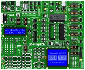
Development system mikroElektronika EasyAVR6
EasyAVR6 is a development system that supports wide range of AVR MCU (8, 14, 20, 28 and 40 pin pin).
Detailed Description
State-Of-The-Art very fast USB 2.0 programmer on-board with simplified driver installation.
USB 2.0 on-board programmer - AVRprog2: You will get the USB programmer which doesn't use boot loader or any similar way of programming.
The whole AVR memory and all pins are available to you. Aside from that, you will have state-of-the-art fast USB AVR InSystem programmer for your future projects. Our latest AVRprog2 Programmer is driven and powered from a single USB port on your computer. No additional AC power adapter is needed. The programmer is recognized by Windows, which simplifies driver installation. The programmer board is specifically designed for In-Circuit Serial Programming (ICSP). Also External Programmer and JTAG can be connected and used with this development system.
EasyAVR6 allows the AVR microcontroller to be interfaced with external circuits to a broad range of the peripheral devices. There is on-board Port Expander (MCP23S17, the 16-bit I/O expander that uses SPI communication). EasyAVR6 contains on-board Touch Screen controller with connector for easier Touch Panel connecting.
Features:
- RS-232 communication with PC or another microcontroller is available via DB9 connector.
- System can be easily configured via clearly marked DIP switches. Each DIP switch configures part of system.
- Digital thermometer DS1820 for measuring temperature from -55°C to 125°C can be connected to system via socket.
- Support for MCU's in DIP8, DIP14, DIP20, DIP28 and DIP40 socket. Board is delivered with ATMEGA16 device.
- Potentiometer is available for testing multiple AD conversion. Input can be configured via jumpers.
- Power Supply select - USB or external, just by moving jumper. Also there is a switch for turning on/off system.
- 2×16 Character COG Display is available on-board for displaying text messages. Display is connected via SPI.
- All pins are connected to IDC10 connectors for further expansion. All pins of these connectors are marked on-board.
- There are 35 LED (Light Emmiting Diodes) for displaying states of all pins on the MCU at the same time.
- There are jumpers on-board that are used for Pull up or Pull down port defining. These jumers are available for all pins.
- There are 35 buttons for program developing needs. These buttons are connected to all microcontrollers pins.
- DIP switch is available on-board for easy separating port pins from Pull up or Pull down resistors.
- There is very fast USB 2.0 programmer on-board. There is no need for connecting external programmer.
- LCD display can be easily connected via connector that can be found on-board. This connector is connected to MCU pins.
- There is LCD Contrast Potentiometer on-board that is used for adjusting LCD Contrast very fast and easy.
- Touch Screen can be connected to the board via Touch screen connector. There is also a Touch Screen controller.
- External power supply can be DC or AC. There is a jumper on-board that is used for selecting external power supply.
- Crystal can be replaced by another one. There are jumpers for configuring pins as oscillator inputs or regular I/O pins.
- Graphic LCD 128×64 can be easily connected via connector that can be found on-board and is connected to MCU pins.
- All pins are marked on the back of the board. These marks describe connections, modes, and some other useful notes.
- Choose voltage level to be applied when a button is pressed (GND or +5V) via on-board jumper that is used for this selection.
- GLCD Contrast Potentiometer is on-board for adjusting Graphic LCD Contrast.
- There is a reset circuit on-board that is connected to the MCLR Pin of the microcontroller.
- On-board USB UART module features the FT232RL - An interface between a USB device and the microcontroller.
- On-board 4×4 Keypad allows efficient entry of numerical data as well as other characters.
- Menu Keypad enables easy and fast menu browsing for your prototype device.
- There is Port Expander on-board if there is need for more inputs or outputs.
- There are connectors on-board for programming with External programmer.
- There is an JTAG port that supports in-circuit debugging and firmware programming.
- On-board COG 2×16 Display contrast potentiometer for adjusting COG.
EasyAVR6 Development System supports wide range of AVR microcontrollers. Newly released AVR microcontrollers will be supported with new version of AVRProg software that is updated regularly.
Examples that comes with this development system will show you how to connect the AVR microcontroller easily with other peripheral components or devices when developing your prototype device. Each example contains detailed description and comments of the program.
Package contains:
- EasyAVR6 development system.
- USB cable.
- CD with software, drivers and examples in C, BASIC and Pascal.
- Printed Documentation that includes: EasyAVR6 Manual, EasyAVR6 Schematic Diagram, AVRprog Manual and Quick Guide for Installing USB Drivers.
