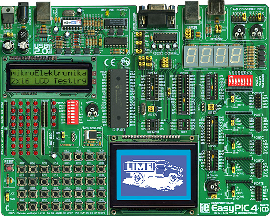
Development system mikroElektronika EasyPIC4
The EasyPIC4 is a full-featured development system for PIC microcontrollers from Microchip.
Detailed Description
There is a USB 2.0 programmer with mikro ICD (In-Circuit Debugger) support provided on the board.
EasyPIC4 KEY FEATURES
- External power supply from 8 to 16 V AC/DC.
- Choose between external and USB power supply. When powering from your PC’s USB port, you don’t need an external supply.
- Very fast and flexible USB programmer on board with mikroICD (In-Circuit Debugger). The key feature is expandability. By downloading new software, you will be able to program new MCUs in coming years.
- DS1820 temperature sensor allows you to measure temperature with 0.5 C accuracy.
- RS232 communications with selectable TX and RX for smaller microcotrollers.
- For presentation purposes, several pins, RA0-RA5 are connected to, and can be used for measuring voltages set by, the potentiometers P1 and P2.
- Port A is connected to a resistor network, using switches SW1. If a switch is in OFF position, the appropriate pin has neither pull-up or pull-down resistor attached. This is very important as it enables PORTA to be used in analog mode as an A/D converter as well as an ordinary digital I/O port.
- Setting the jumper to the upper position sets the pins of the appropriate port to logical one (pull-up). If the jumper is set to the lower postion, pins are set to logical zero (pull-down). It is very important to select pull-up for a port if you expect logical zero on its inputs and vice versa.
- You can connect an LCD if you need it for your application in 4-bit mode.
- You can connect a Graphic LCD if you need it for your application or LCD in 8-bit mode.
- EasyPIC4 supports microcontrollers in DIP8, DIP14, DIP18, DIP20, DIP28 and DIP40 package, which means you are ready to use almost the entire range of Microchip Microcontrollers.
- 36 buttons allow you to control every pin on your microcontroller.
- You can choose how pressing the button will affect the pin, high state or low state.
- See all the signals - each pin has an LED.
- Seven segment displays in multiplex mode for displaying values.
- Turns ON or OFF the LEDs on ports A, B, C, D and E. You can choose which port you want LEDs to be connected to. Also, you can choose which digit you want to be on. In certain applications, it is important to remove all unnecessary connections from pins - these DIP switches let you disconnect all LEDs and digits from MCU pins.
- Set LCD contrast according to your needs.
- Power supply control.
- USB communication for MCUwith USB support.
- PC keyboard connector.
- Reset circuit - if the reset button is pressed a hardware reset will take place (MCU will start executing from the beginning).
EasyPIC4 development board schematic diagram
Other Names:
MEEASYPIC4, EASYPIC4, ME EASYPIC4, EASYPIC4, ME-EASYPIC4 EASYPIC4, ME-EASYPIC4 EASYPIC4
