All Sections: LT Spice - 10
Search for: "LT Spice"
- Datasheets Analog Devices MAX6006AEUR+1µA SOT23 Precision Shunt Voltage Reference SOT23 Voltage Reference Draws Only 1µA! The MAX6006 MAX6009 ultra-low-power shunt references are ideal for space-critical and low-power applications. They are offered in 3-pin SOT23 packages, ...Nov 16, 2024
- Datasheets Analog Devices MAX6006AEUR+T1µA SOT23 Precision Shunt Voltage Reference SOT23 Voltage Reference Draws Only 1µA! The MAX6006 MAX6009 ultra-low-power shunt references are ideal for space-critical and low-power applications. They are offered in 3-pin SOT23 packages, ...Nov 16, 2024
- 1µA SOT23 Precision Shunt Voltage Reference SOT23 Voltage Reference Draws Only 1µA! The MAX6006 MAX6009 ultra-low-power shunt references are ideal for space-critical and low-power applications. They are offered in 3-pin SOT23 packages, ...Nov 16, 2024
- Datasheets Analog Devices MAX6006BESA+1µA SOT23 Precision Shunt Voltage Reference SOT23 Voltage Reference Draws Only 1µA! The MAX6006 MAX6009 ultra-low-power shunt references are ideal for space-critical and low-power applications. They are offered in 3-pin SOT23 packages, ...Nov 16, 2024
- Datasheets Analog Devices MAX6006BESA+T1µA SOT23 Precision Shunt Voltage Reference SOT23 Voltage Reference Draws Only 1µA! The MAX6006 MAX6009 ultra-low-power shunt references are ideal for space-critical and low-power applications. They are offered in 3-pin SOT23 packages, ...Nov 16, 2024
- Datasheets Analog Devices MAX6006BEUR+1µA SOT23 Precision Shunt Voltage Reference SOT23 Voltage Reference Draws Only 1µA! The MAX6006 MAX6009 ultra-low-power shunt references are ideal for space-critical and low-power applications. They are offered in 3-pin SOT23 packages, ...Nov 16, 2024
- Datasheets Analog Devices MAX6006BEUR+T1µA SOT23 Precision Shunt Voltage Reference SOT23 Voltage Reference Draws Only 1µA! The MAX6006 MAX6009 ultra-low-power shunt references are ideal for space-critical and low-power applications. They are offered in 3-pin SOT23 packages, ...Nov 16, 2024
- 1µA SOT23 Precision Shunt Voltage Reference SOT23 Voltage Reference Draws Only 1µA! The MAX6006 MAX6009 ultra-low-power shunt references are ideal for space-critical and low-power applications. They are offered in 3-pin SOT23 packages, ...Nov 16, 2024
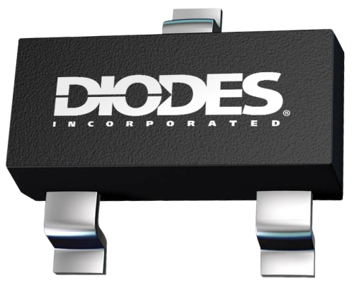
- Datasheets Diodes ZXRE1004DFTANov 12, 2024
- Datasheets Diodes ZXRE1004EFTANov 12, 2024
Sort by: relevance / date
