All Sections: LT Spice
Search for: "LT Spice"
- Datasheets Analog Devices LT8418ACBZ-R7
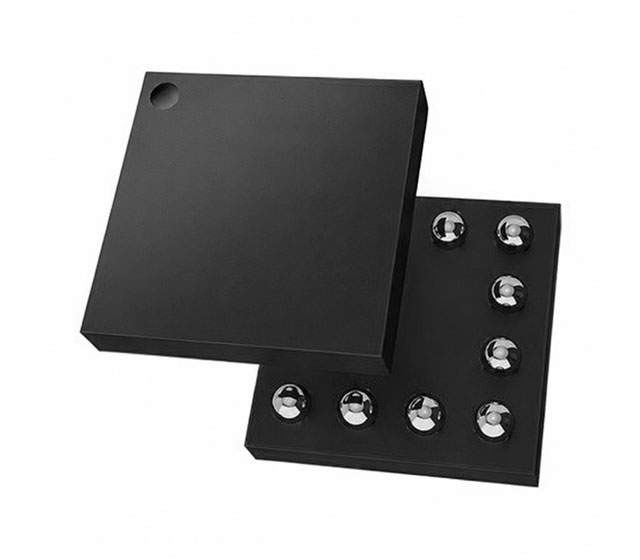 100V Half-Bridge GaN Driver with Smart Integrated Bootstrap Switch in WLCSP-12 (1.67x1.67) package The LT8418 is a 100V half-bridge GaN driver that integrates top and bottom driver stages, driver logic control, and protections. It can be configured ...Jun 17, 2026
- 100V Half-Bridge GaN Driver with Smart Integrated Bootstrap Switch in WLCSP-12 (1.67x1.67) package The LT8418 is a 100V half-bridge GaN driver that integrates top and bottom driver stages, driver logic control, and protections. It can be configured ...Jun 17, 2026
- Jayapal RamalingamCircuits STMicroelectronics LM124Ground-referenced loads are common in industry. This circuit implements current loop conversions for them. Recently, there have been several published Design Ideas on converting 0/20 mA to 4/20 mA current and 4/20 mA to 0/20 mA current as ...May 25, 2026
- Jayapal RamalingamCircuits Texas Instruments LM124Circuits such as the design described here implement useful tools for a diversity of calibration and testing applications A two-wire loop current generator is a useful tool for the testing, calibration and commissioning of current-to-pressure (I/P) ...Apr 24, 2026
- Datasheets ON Semiconductor MBRS240LT3G
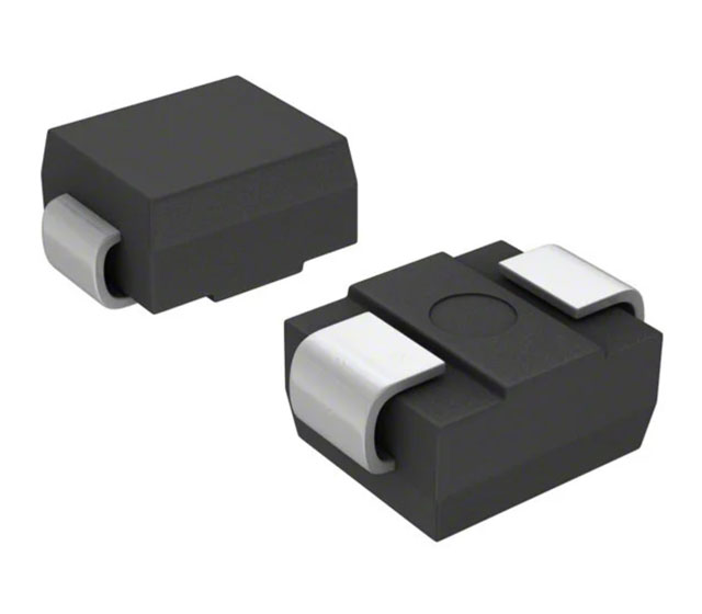 Schottky Power Rectifier, Surface Mount, 2.0 A, 40 V in 403A-03 package The Schottky Rectifier employs the Schottky Barrier principle in a metal-to-silicon power rectifier. It features epitaxial construction with oxide passivation and metal overlay ...Apr 21, 2026
 - Datasheets ON Semiconductor NRVBS240LT3GSchottky Power Rectifier, Surface Mount, 2.0 A, 40 V in 403A-03 package The Schottky Rectifier employs the Schottky Barrier principle in a metal-to-silicon power rectifier. It features epitaxial construction with oxide passivation and metal overlay ...Apr 21, 2026
- Datasheets ON Semiconductor MBRS240LT3Schottky Power Rectifier, Surface Mount, 2.0 A, 40 V in 403A-03 package The Schottky Rectifier employs the Schottky Barrier principle in a metal-to-silicon power rectifier. It features epitaxial construction with oxide passivation and metal overlay ...Apr 21, 2026
- Datasheets ON Semiconductor MBRS240LT3HSchottky Power Rectifier, Surface Mount, 2.0 A, 40 V in 403A-03 package The Schottky Rectifier employs the Schottky Barrier principle in a metal-to-silicon power rectifier. It features epitaxial construction with oxide passivation and metal overlay ...Apr 21, 2026
- Jayapal RamalingamCircuits Texas Instruments LM124In process industries, field contacts from pressure, temperature, flow switches, limit switches, push buttons, etc., are read by programmable logic controllers and/or distributed control systems (PLC/DCS) through digital input modules. They are ...Mar 27, 2026
- Stephen WoodwardCircuits Texas Instruments LMC555 LTC2066The pages of Design Ideas (DIs) have recently been awash in a veritable cascade of designs for variable frequency oscillators with frequency ranges tunable over multiple decades: Self-oscillating sawtooth generator spans 5 decades of frequencies ( ...Mar 26, 2026
Sort by: relevance / date