Ground-referenced loads are common in industry. This circuit implements current loop conversions for them.
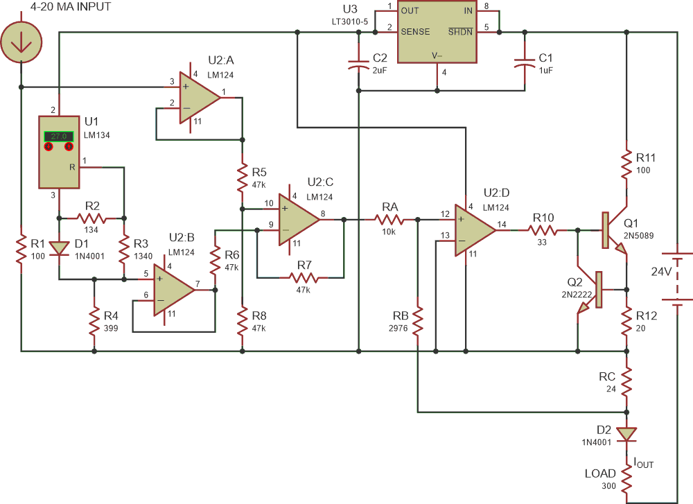
Recently, there have been several published Design Ideas on converting 0/20 mA to 4/20 mA current and 4/20 mA to 0/20 mA current as full-circle current loop conversions. However, these circuits have all focused on floating loads. It’s common to also come across loads that are ground-referenced. The circuit in Figure 1 addresses this alternative requirement, converting 4/20 mA current to 0/20 mA current for feeding grounded loads.
 |
|
| Figure 1. | In this 4/20 mA to 0/20 mA converter for grounded loads, R4 and RB can be replaced by multi-turn potentiometers for tuning purposes. |
How does it work? Input current of 4-20 mA feeds into R1 and is converted into 0.4 V – 2.0 V, which is buffered by U2A. U1 generates a reference current of 1 mA which is fed into R4, and which converts it to 0.4 V. This converted current is buffered by U2B. U2C subtracts the two voltages.
Next, let’s look at the positive input of U2D. There are two currents:
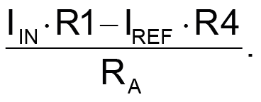
One current going through RA =
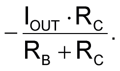
Another current going through RB =
Since the negative input of U2D is grounded, these two currents must be same:
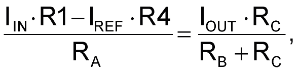
where IREF × R4 = 0.4 V
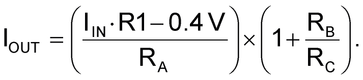
Select the values of RB and RC such that RB/RC = 124. Substituting the values of RA, RB, RC and R1 from Figure 1:
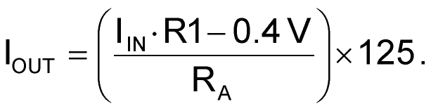
Hence,

For example, if the IIN is 20 mA,

And if the IIN is 4 mA,

How do you tune the circuit? Implement R4 and RB as multi-turn potentiometers. R1 conversely should be a precision 100 ohm resistor. Adjust R4 such that voltage across it is 0.4 V. Feed 20 mA current from the precision current source as the IIN and adjust RB to get 20 mA as IOUT. Repeat this exercise by feeding the circuit with 4 mA and 12 mA.
Simulation test results are shown in Table 1.
| Table 1. | Simulation test results | ||||||||||||||||||||||||||||||||||||||||
|
|||||||||||||||||||||||||||||||||||||||||
These results suggest that the circuit delivers high accuracy, with error no higher than 0.5%, except with a 4 mA input. The error and associated accuracy can be improved by selecting high-end operational amplifiers such as instrumentation amplifiers with negligible offset and a high common-mode rejection ratio (CMRR).
Q2 prevents the output current from exceeding a few mA above the 20 mA input threshold, as a safety measure. R5, R6, and R7 should be identical in value. And also implement R8 as a multi-turn potentiometer. The resultant tuning capability helps to reduce the output to near-zero for a 4 mA input.