By Doug Mercer, Analog Devices
Various software packages enable the stereo sound card found in a personal computer (PC) to provide oscilloscope-like displays, but the low-sample-rate, high-resolution analog-to-digital converters (ADCs) and ac-coupled front end are optimized for 20 kHz or less of usable bandwidth. This limited bandwidth can be extended – for repetitive waveforms – by using a sampling front end ahead of the sound card inputs. Subsampling the input waveform with a high-speed sample-and-hold amplifier (SHA) – followed by a low-pass filter to reconstruct and smooth the waveform – effectively stretches the time axis, allowing the PC to be used as a high-speed sampling oscilloscope. This article describes a front end and probe that provide an appropriate adaptation.
Figure 1 shows a schematic for a plug-in attachment that can be used for sampling with typical PC sound cards. It uses one AD783 high-speed sample-and-hold amplifier per oscilloscope channel. The sampling signal for the SHA is provided by the digital output of a clock-divider circuit; an example of one will be described. The AD783 input is buffered by a FET, so simple ac/dc input coupling can be used. In the two channels shown, 1-MΩ resistors (R1 and R3) provide dc bias when the dc-coupling jumper is open and the input is ac-coupled. The sampled output is low-pass filtered by the two-pole active RC networks shown. The filter need not be an active circuit, but the one shown usefully provides a buffered low impedance to drive the PC sound-card input.
 |
|
| Figure 1. | 2-channel analog sampling circuit. |
The AD783 SHA provides a usable large-signal bandwidth up to a few megahertz. The effective slew rate at the input is above 100 V/µs. Input/output swing with a ±5-V supply is at least ±3 V. The small-signal 3-dB bandwidth for swings less than 500 mV p-p is close to 50 MHz.
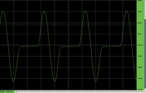
With the front-end circuit of Figure 1, and a PC’s sound card employing the Visual Analyser1 software, the screen shot in Figure 2 illustrates a 2-MHz, single-cycle sine repeated at 1 MHz. The sampling clock provides 250-ns-wide sample pulses at an 80.321-kHz sample rate. The effective horizontal time base here is 333 ns/division. The PC sound card used in these examples uses an Analog Devices SoundMax codec sampling at 96 kSPS. In this example, the effective sampling rate is about 40 MSPS.
 |
|
| Figure 2. | 2-MHz single-cycle sine pulse at 1-MHz repetition rate. |
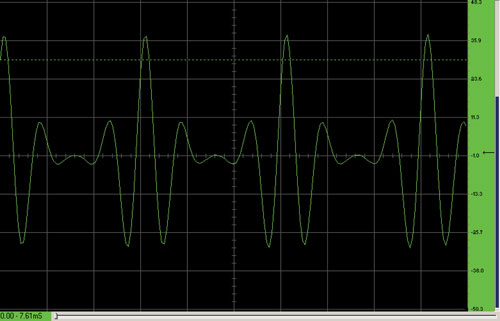
Another screen shot was taken of a Gaussian sine pulse with a 1-MHz repetition rate (Figure 3). The sampling clock rate was again 80.321 kHz, with 250-ns sample pulse width.
 |
|
| Figure 3. | 4-MHz Gaussian sine pulse at 1-MHz repetition rate. |
Example of a Sampling Clock Generator
The AD783 requires a narrow positive sampling pulse with a width between 150 ns and 250 ns. The sampling pulse must be very stable with low jitter in order for the displayed waveform to be stable without jumping back and forth. This requirement tends to limit possible clock choices to crystal-based oscillators. Another requirement is that the sampling rate be adjustable or tunable over a range from slightly less than 100 kHz to about 500 kHz. The tuning steps between sampling frequencies need to be relatively fine for downsampled signals to fall somewhere within the 20 Hz to 20 kHz audio bandwidth of the sound card. A divide-by-N circuit, such as that shown in Figure 4, and a crystal oscillator with a frequency between 10 MHz and 20 MHz (IC4), can provide up to 200 or more different sample rates from 80 kHz to 350 kHz, with step sizes from 300 Hz to 5 kHz.
 |
|
| Figure 4. | Sampling clock divider circuit. |
In this example, using two 74HC191 4-bit binary up/down counters, N can be any integer between 4 and 256. Alternatively, decade counters, such as the 74HC190, with identical pinouts to the 74HC191, could be used to provide a range of N from 4 to 100. The division ratio is set using the two hex switches, S1 and S2. Switch S3 sets the counters to count up or count down. Resistor R1 (250 Ω) and capacitor C1 (68 pF) add a slight delay to the terminal count output before it asynchronously loads the start-count values. The four NAND gates of the 74HC00 are used to implement a one shot that makes a 200 ns sample pulse when R12 is 2.7 kΩ and C2 is 68 pF.
IC4 is a fixed-frequency metal-can crystal oscillator. Another approach would be to use CMOS inverters (74HC04) and a discrete crystal, X1, to form an oscillator, as shown in Figure 5. This approach, while using more components than the all-in-one metal-can oscillator, permits a small amount of frequency tuning by adjusting capacitor C1 to pull the crystal frequency.
 |
|
| Figure 5. | Discrete crystal oscillator with mechanical tuning. |
To avoid the mechanically variable component, use a varactor diode – which has voltage-dependent capacitance – for D1, as shown in Figure 6.
 |
|
| Figure 6. | Discrete crystal oscillator with voltage tuning. |
Part 2 - Active Reconstruction Filters, Powering the Circuits, Input Attenuators