Part 1 - Specifications and Schematic
The data is recorded as the Comma Separate Value (CSV) file to the SD/MMC memory card. The interval between sample is programmable from 10 secs to 60 mins. The optional digital input signal, pulse, and frequency measurement are also provided.
Memory Card Preparation
The memory card can be SD or MMC standard size with storage capacity up to 2GB. The card must be formatted using FAT file type. The new memory cards that used in digital camera usually are preformatted with FAT.
Setup File
To set the internal clock, interval and station name, the setup file must be prepared. The setup file is a simple text file. It can be created using any text editor program. The file name must be "auto_exe.txt". The text content is as follows.
HH:MM DD/MM/YY I N
07:00 05/02/2009 1 A
The example sets internal clock to 7:00, date to 5 Feb 2009, interval (I) to 1 minute and station name (N) to A. Each field must be separated by one space.
Operating procedures
- Insert the mempry card. Switch on the device.
- The LED shows RED blinking.
- The device is detecting the memory card.
- GREEN LED shows the memory card found and the data file will be created with a given station name e.g. ADATA000.CSV.
- GREEN LED blinks every 4 secs scanning the input signals.
- Within the preset interval, the RED LED blip once showing the record is writing to the memory card.
- To remove the card, switch off, push the card to unlock it..
- The data file can be transferred to the PC easily using the memory card reader.
- When insert the same memory card, the next data file will be created sequencially as ADATA001.CSV.
Note. For next experiment. No need to make the setup file again. However if need to change the clock, interval or station name, user can create the new setup file.The new settings will be updated automatically.
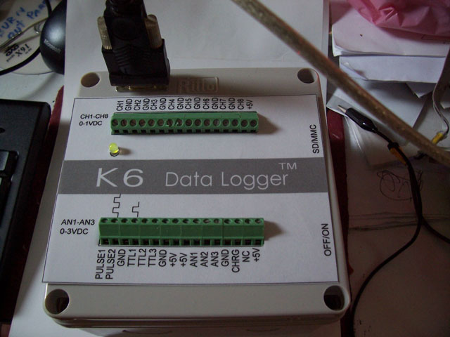
Analog Input Terminal
The analog input terminal (CH1 to CH8) accepts 0-1VDC single end input. Pin 16 provides +5V for the sensors that need power supply.
Example for LM35 temperature sensor connected to CH1.
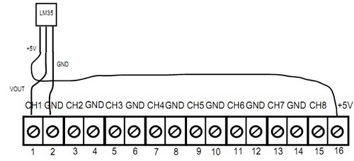
The reading resolution for CH1 to CH8 is 1 microVolt. The maximum source resistance is 1 kOhm.
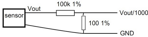
+10VDC Analog Input Signal
For larger amplitude DC signal, e.g. the sensors that produce +10V full scale, we can make 1000 times voltage divider using 100k Ohms and 100 Ohms 1/8W resistors. The circuit is shown below. The reading appeared in the record will be 1/1000 of the input signal.
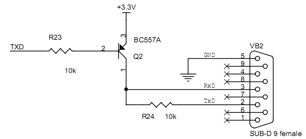
K6 version with RS232 port
Here is the additional circuit for the K6 version. The simple RS232 logic translation from +3V positive logic to the RS232 logic.
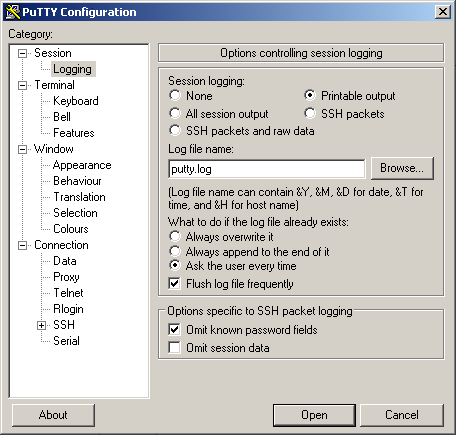
The small program, PuTTY is used to capture and display the data sent from the data logger.
To capture data stream, select Session-Logging and mark at the Printable output. The sample log file name, putty.log is shown below.
Now select Session, click at the Serial and type the COM port, shown the COM2. Then click OPEN.
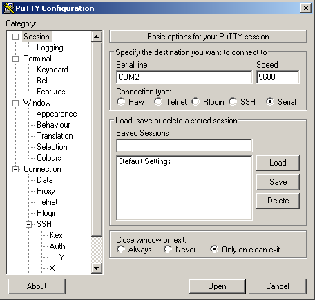
The terminal screen will show. When the reading is saved to the memory card, it will send to the serial port as well. On the terminal screen we can see the real-time data stream. This data streams are composed of ASCII code, or printable output, so it will be saved in the log file concurrently.
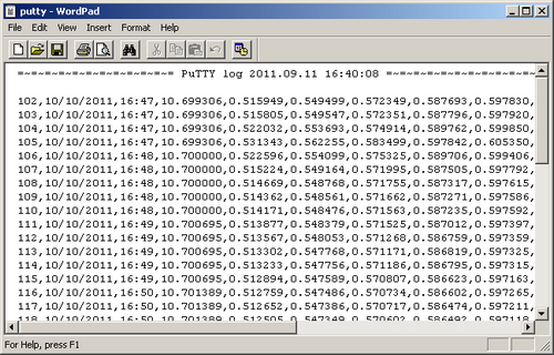
And here is the sample log file content. The contents are comma separate value, CSV, so it can be imported into a spreadsheet software easily.
Downloads
Firmware for K6 version - download