Thomas Mathews, Texas Instruments
EDN
For battery-powered circuits, it is easy to build an ultralow-current crystal oscillator designed around a 32.768-kHz crystal. This crystal is common for real-timeclock circuits. Because these circuits must operate at all times, achieving the lowest current draw possible is mandatory. Traditional gate-oscillator circuits – the 74HC04, for example – can draw several milliamps; the circuit shown in Figure 1 normally draws only about 5 µA. This circuit uses the Texas Instruments LPV7215MF comparator, which is housed in a five-pin SOT-23 package. The operating current for this comparator is 580 nA; the entire circuit shown in Figure 1 draws only 5 µA when running from a 3.3V supply.
 |
|
| Figure 1. | Traditional gate-oscillator circuits can draw several milliamps; the circuit shown normally draws only about 5 μA. |
Multiple copies of this circuit have been built and tested to confirm the 5-µA current draw. The largest portion of the 5 µA goes to the largely unavoidable operations of charging and discharging the output load capacitance. The circuit was tested using a standard 10-MΩ oscilloscope probe with about 10 pF of shunt capacitance; operating current into more capacitive loads will be higher. Table 1 breaks down the power consumption piece by piece.
Capacitive loads must be charged by the upper transistor in the active output stage of the LPV7215. To charge a capacitor to 3.3V, note the capacitor equation
Q=C×V.
This charge is transferred into the capacitance during the first half of each cycle of the 32.768-kHz oscillation. During the second half, the charge is transferred to ground. As a result, the output-stage current, i, will be
i=f×Q=f×C×V.
For 20 pF (a 10-pF scope probe plus a PCB parasitic),
i=(32.768 kHz) (20 pF) (3.3V)=2.163 µA.
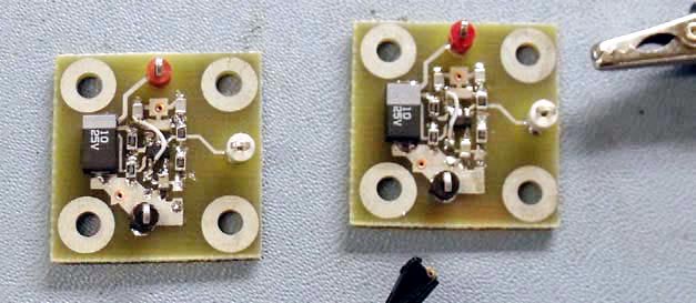
From the equation above, it can be seen that additional output loading or higher operating frequencies will draw more output current. Anything that can be done to reduce the capacitive load will reduce the total current draw. Figure 2 shows an example of the test boards used to create the crystal-oscillator circuit.
 |
|
| Figure 2. | Test boards of a crystal-oscillator circuit are based on the Texas Instruments LPV7215MF comparator. |
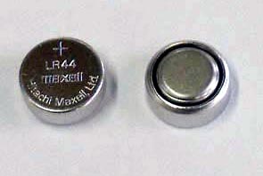
Typical LR44 alkaline button-cell batteries (Figure 3) have a capacity of 150 mAhr. With 5 µA of current draw, this clock circuit could run for about 30,000 hours, or 3.4 years.
 |
|
| Figure 3. | Typical LR44 alkaline button-cell batteries supply 150 mAhr of capacity. |
Table 1. Loading estimates
|
Source
|
Supply current (μA)
|
|
LPV7215MF
|
0.58
|
|
R1 and R2 bias
|
0.33
|
|
R3
|
0.083
|
|
Crystal network (estimated)
|
2
|
|
10-MΩ probe load
|
0.165
|
|
20-pF load capacitance
|
2.163
|
|
Estimated total
|
5.321
|
|
Actual total
|
5
|