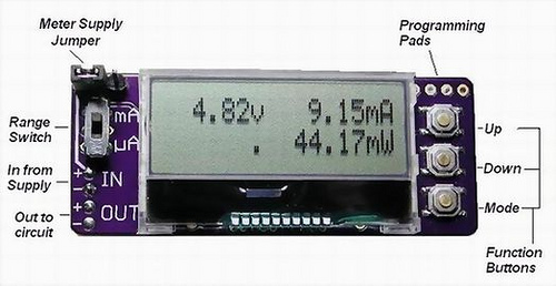
The Power Scope is a meter intended for use on a breadboard to aid in the development of battery-operated devices. It provides dedicated monitoring at the power source so you can quickly see the effects of circuit/software changes on power consumption during development. This frees up your DVM for general diagnostic use (Figure 1).
 |
|
| Figure1. | MSP430 Powerscope provides dedicated monitoring at the power source. |
The PowerScope is able to sample voltage and current, and compute the power draw, at a 1kHz rate. This allows it to accurately compute average power consumption in devices where portions of the circuit are periodically shut down to conserve power, such as sensor controllers. The display is updated once per second, and power is averaged over a five second interval.
PowerScope Specs
- Voltage measured from 0-10.0vdc at .01v resolution
- Current measured 0-300.0mA at .01mA resolution (High Range)
- Current measured 0-300.0uA at .01uA resolution (Low Range )
- Reverse voltage protected
- Maximum Burden Voltage = 0.3v
- Meter itself consumes 8.5mA from a 5.4v supply
- Power source can be +3.5v to +10.0vdc
- Inputs are Overvoltage protected up to +/- 40.0vdc
- Sample update rate = 1khz
- Voltage zeroing and calibration functions via function buttons
- Current zeroing and calibration functions for mA and uA ranges
- Current measurement is done "low side" on circuit ground return path
- Dimensions 1.0” x 2.6”
Schematic(Figure 2)
 |
|
| Figure 2. | PoerScope Schematic Diagram. |
The MSP430G2402 series of microcontrollers are ultra-low-power mixed signal microcontrollers with built-in 16-bit timers, and up to 16 I/O capacitive-touch enabled pins and built-in communication capability using the universal serial communication interface. Typical applications include low-cost sensor systems that capture analog signals, convert them to digital values, and then process the data for display or for transmission to a host system.
The AD8226 is a low cost, wide supply range instrumentation amplifier that requires only one external resistor to set any gain between 1 and 1000. The AD8226 is designed to work with a variety of signal voltages. A wide input range and rail-to-rail output allow the signal to make full use of the supply rails. Because the input range also includes the ability to go below the negative supply, small signals near ground can be amplified without requiring dual supplies. The AD8226 operates on supplies ranging from ±1.35 V to ±18 V for dual supplies and 2.2 V to 36 V for single supply.
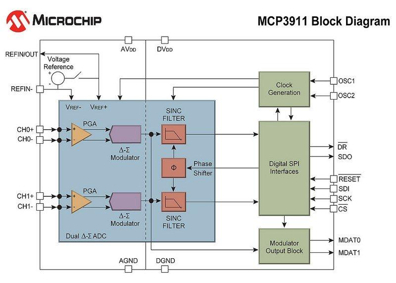
The MCP3911 (Figure 3) is a 2.7V to 3.6V dual channel Analog Front End (AFE) containing two synchronous sampling Delta-Sigma Analog-to-Digital Converters (ADC), two PGAs, phase delay compensation block, internal voltage reference, modulator output block, and highspeed 20 MHz SPI compatible serial interface. The MCP3911 is capable of interfacing a large variety of voltage and current sensors including shunts, current transformers, Rogowski coils and Hall effect sensors.
 |
|
| Figure 3. | MCP3911 Block Diagram. |
Warning:
The PCB is designed to accept 1206 size surface-mount resistors for the two shunt resistors of 1 ohm and 1000 ohm, nominally 1/4 watt rated. If the OUT power connection were shorted to ground, or connected to load of less than 20 ohms, while switched to the mA range, the 1-ohm shunt resistor could be damaged.
Connections
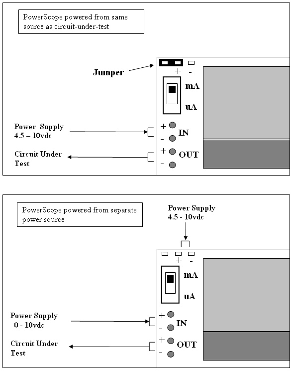
The PoweScope can be powered from the same supply as the circuit, or from a separate source, as shown below (Figure 4):
 |
|
| Figure 4. | PoweScope can be powered from the same supply as the circuit, or from a separate source. |
Programming
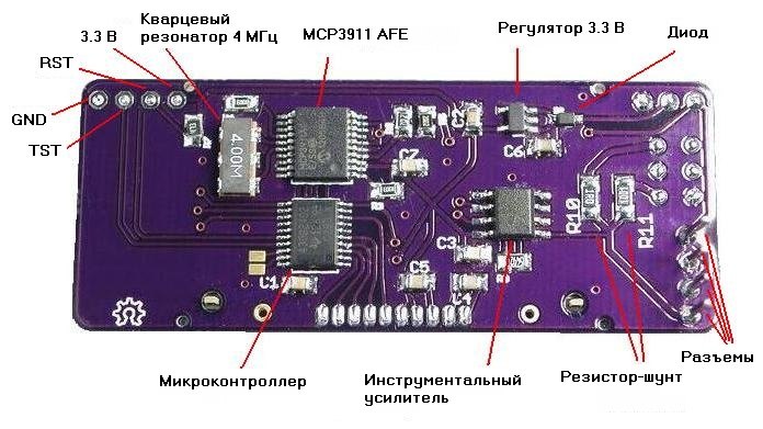
The PowerScope has a T.I MSP430G2402 microprocessor programmed in C using the Code Composer Studio. Program ROM is flashed using a T.I. LaunchPad, connected to a Windows PC via USB cable. A four-wire cable is used to connect the Launchpad to the four programming pads on the upper corner of the board (Figure 5).
 |
|
 |
|
| Figure 5. | PowerScope Component Placement. |
Note the unused pads next to the processor chip. They are there to add a crystal for more precise time measurement if a user wants to program a display of cumulative mA-hours, for example.
Calibration
Calibration is done in the software to avoid the need for tight-tolerance components.
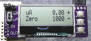
Voltage and current measurements are calibrated and zeroed using the function buttons. A trusted multimeter can be used to calibrate volts and mA by connecting a power source to a resistor and measuring the current flow with both meters. Then, a high-value precision resistor can be used with a voltage source to calibrate the uA current range at values too small for the multimeter.
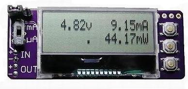
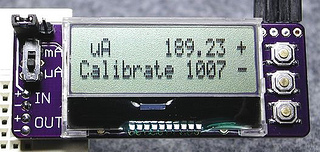
The mode button selects which value to zero/calibrate, then the up(+)/down(-) buttons will make adjustments. The measured value in the upper right will change in real time. The calibration constant used in the software is displayed on the lower right. The range switch position determines whether the mA or uA range is being calibrated (Figure 6). When you exit calibration mode, the calibration constants are saved in the “Info” section of the MSP430 flash ROM.
 |
|
 |
|
| Figure 6. | Calibration is done in the software to avoid the need for tight-tolerance components. |
The calibration constants are multipliers used in the code to adjust values to compensate for variances in the component values. If you find you need to adjust the calibration to where the constant is above 1200 or below 800, you might want to look at the shunt resistors or the instrumentation amp gain resistor for damage or out-of-tolerance condition.
Shunt Resistor Options
Important
The PowerScope has been tested with lower shunt resistors of .1ohm for mA range and 100 ohm for uA range. The advantage of the lower shunts is that it drops the maximum burden voltage from 300mV to 30mV.
If you want to use the lower value shunt resistances, there is a line you can un-comment in v1.1 of the code:
// #define LOW_SHUNTS
Then:
- Replace the 1.0 ohm shunt with .1 ohm (Digikey P100LPCT-ND)
- Replace the 1000.0 ohm shunt with 100.0 ohm (DigiKey P100FCT-ND)
- Replace the 54.9K gain resistor with 4.99k (DigiKey P4.99KCCT-ND)
NOTE: The contact resistance of the switch becomes significant when using these shunt values, since the measurement is done across both the resistor and the switch on the PowerScope. Your switch's contact resistance may exceed the manufacturer spec and make it hard to calibrate the unit without changing the source code.
Demonstration (Figure 7, 8)
 |
|
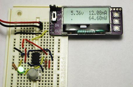
| Figure 7. | Measuring power consumption of a 555 timer circuit generating a 100Hz signal. Here the PowerScope is powered from the same 5v supply as the circuit under test. |
 |
|
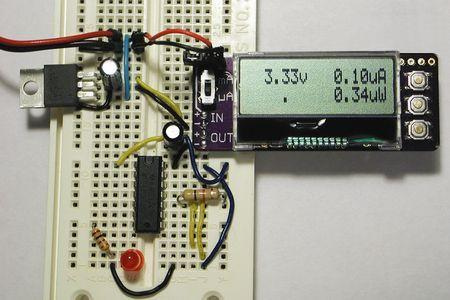
| Figure 8. | Measuring power drawn by a T.I. MSP430G2211 processor in low-power mode 4. Chip spec states nominal .1uA consumption. Here the PowerScope is powered from the 5v source, but it measures the 3.3v regulator output used to power the processor. |
Downloads
Source Code, Firmware, Schematic and PCB (Eagle), BOM - download