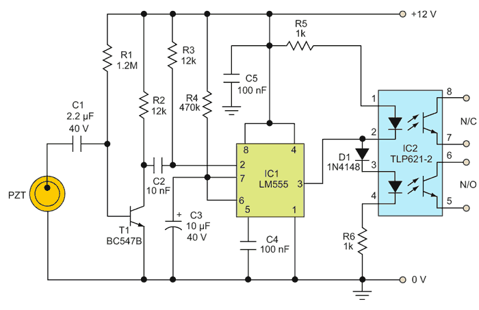
Although piezoelectric elements have been used for shock and vibration detection for some time, this circuit provides a low-cost alternative for solid-state general-purpose impact sensing. The circuit uses a standard piezoelectric device (PZT) to detect a mechanical shock or vibration in its vicinity (see the Figure 1).
 |
|
| Figure 1. | When the piezoelectric device (PZT) detects a mechanical impact, it emits a signal that triggers the monostable (IC1), which in turn controls the output of the dual LED/phototransistor opto-coupler (IC2). |
The output of IC1, and LM555 monostable, initially is low. When an impact flexes the PZT, it generates a voltage. The base of transistor T1 is biased using the PZT, so the transistor amplifies the sensor signal, which triggers IC1’s input (pin 2) and changes the IC’s state.
IC1’s output (pin 3) goes high for a finite time determined by the values of timing components R4 and C3. IC1’s output is routed to the inputs (pin 2 and pin 3) of IC2, a dual-LED and phototransistor opto-coupler in an eight-pin plastic dual-inline package (TLP621-2).
When IC1’s output is low, IC2’s first LED (across pins 1 and 2) lights and activates the first phototransistor (across pins 7 and 8). When the monostable’s output goes high, the first LED goes out and the second LED (across pins 3 and 4) lights, switching on the second phototransistor. The result is a solid-state dual-mode output (N/C and N/O) from IC2 that can be interfaced with an external circuit. You may need to alter the values of R5 and R6 in some applications to optimize the switching in IC2.
After constructing the circuit on a Veroboard, enclose it in a suitable ABS cabinet. Then connect the PZT to the circuit using a short length of shielded cable. Glue a rounded rubber washer on the face plate of the piezo element and attach it to the required surface with the washer facing the surface so the PZT can flex to detect impacts.