Clive Bolton
EDN
This Design Idea drives the ±20mA current loops that are often used to control two-way proportional pneumatic or hydraulic servo valves in high power robotics applications. Most current drivers are capable of driving unipolar outputs only. Bipolar current drivers often require negative supply voltages.
The circuit operates from a single supply, uses dual or quad components in very small packages, and takes up very little board space. A set of four drivers may be built in less than two square inches of board real estate, including connectors.
Opposing output MOSFET pairs Q1A/Q3B and Q1B/Q3A are enabled to send either positive or negative current to the valve. Current sense resistor R3, connected to the output MOSFET source leads, feeds back the current to wide operating range rail-to-rail I/O op-amp U1. RS1D, C1, and U1A form an integrating amplifier that turns on the MOSFET output stage in proportion to the voltage applied at the I_CONTROL input.
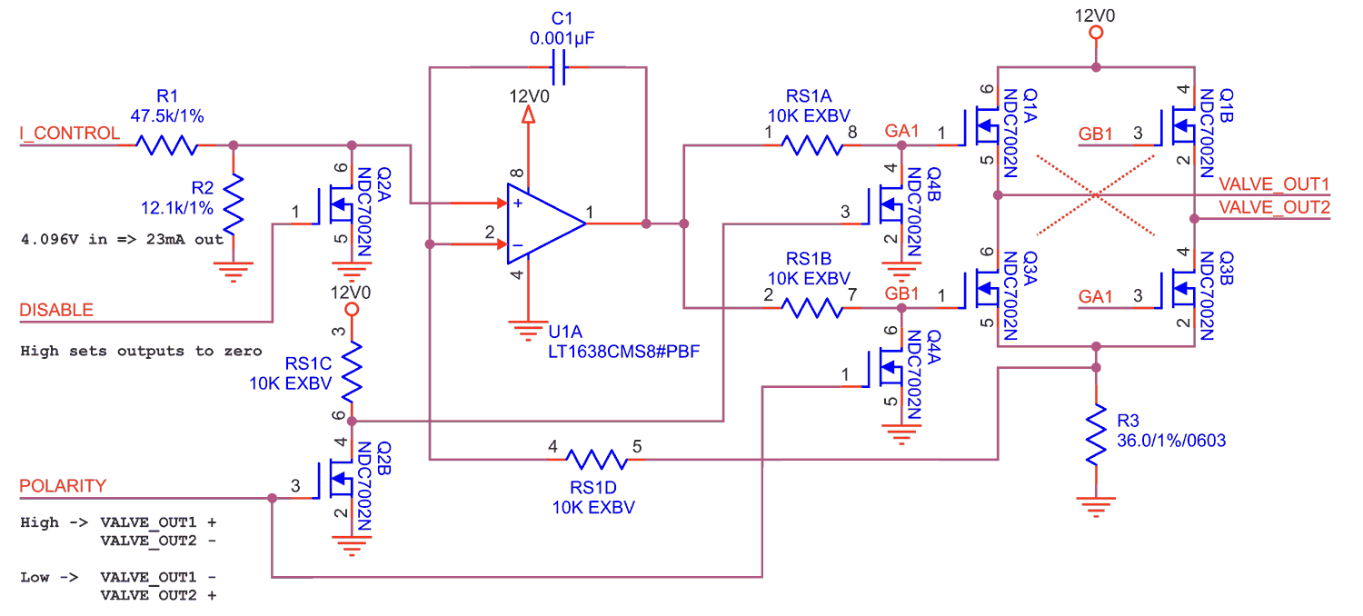
The current output range is set by resistor divider R1 and R2 in conjunction with sense resistor R3:
| |
(1) |
Setting the DISABLE input high turns on Q2A and forces the control voltage into integrator U1A to zero volts, resulting in zero current output. When the POLARITY input is low, Q4B’s gate goes high, forcing Q1A and Q3B off. Q4A’s gate is low, allowing Q1B and Q3A to be controlled by U1. When the POLARITY input is high, Q4A’s gate is high, forcing Q1B and Q3A off. Q4B’s gate is pulled low, allowing Q1A and Q3B to be controlled by U1A.
The driver output voltage is limited by the op-amp supply voltage. The maximum drive voltage with the shown values is:
| |
(2) |
Notes: Resistor pack RS1 is Panasonic EXB-V8V103JV, all MOSFETs are Fairchild duals, type NDC7002N.