By Shawn Rhen
Digi-Key
The advancements in high powered LEDs have brought them to the attention of the lighting industry, positioning them as replacements for the current incandescent and fluorescent technologies. Although widespread adoption has not yet come to fruition, opportunities exist in which these present lighting technologies are unable to compete, a fact that has been realized by lighting architects for years.
Most prevalent is the ability to produce multi-colored illumination for accent, automotive, and signage applications. It is this aspect of high powered RGB LEDs on which we will focus.
In order to produce consistent and repeatable colors, the first design criteria that must be met is that of a constant drive current for each of the RGB die. As shown in Figure 1, this is accomplished utilizing 1 amp maximum constant current drivers that are adjustable with trimmer potentiometers and powered from a 5 volt DC supply.
 |
|
| Figure 1. | Constant current drive circuit. |
With a 500 millivolt minimum above VF of the LED die, this circuit allows control over the individual RGB die currents with a range from around 100 mA up to 1 amp. As the drivers have characteristics similar to those of a linear regulator, the voltage supply to the anodes of the LEDs should be relatively close to the LED forward voltage to prevent the drivers from having to dissipate excess power.
The current passing through the sense resistance is amplified by an internal current amplifier with a gain of around 400. Due to this relatively small sense current, the required wattage rating on the sense resistors is small enough to allow the use of digital potentiometers if so desired.
This circuit works well for testing individual RGB LEDs to determine the required current through each die to produce a desired color. It further allows thermal management testing, as well as a means of comparing RGB LEDs from different manufacturers under similar conditions.
While functional, the circuit’s manual adjustment of trimmer potentiometers is a rather mundane task. In the interest of convenience, the addition of a microcontroller to provide PWM signals to the enable pins of the drivers can be incorporated as shown in Figure 2.
|
|
| Figure 2. | MCU providing PWM signals to the LED drivers. |
The addition of the microcontroller adds a variety of control functionality through the utilization of its on-board USART. Literally any device capable of providing RS-232 communication can be interfaced to control the intensity of the individual red, green, and blue die by varying the PWM duty-cycle.
To implement the RS-232 control effectively, it is necessary to first set up the drive currents to the individual RGB die to produce a white light output. This is accomplished by tying the enable lines high to represent a 100 percent duty-cycle, and adjusting the individual RGB die currents manually with the trimmer potentiometers.
These drive currents should be set to the maximum level (up to 1 amp) required by the application to produce sufficient white light output. Once the die currents are set, varying the duty-cycle on the PWM outputs from the microcontroller will produce relative light output from each die, resulting in a desired color.
Again, the variations in the PWM duty-cycles are obtained from an input to the UART via an RS-232 enabled device. These devices can range from a PC serial port, a USB virtual COM port, or a wireless module using protocols such as Bluetooth or ZigBee.
 |
|
| Figure 3. | Wireless connectivity example. |
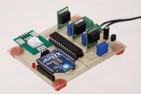
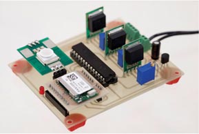
While the serial and USB ports work well for wired applications, wireless modules can provide control from various remote locations. The example application shown in Figure 3 utilizes a ZigBee to Ethernet gateway along with a ZigBee module for wireless communication to the gateway and the RGB color mixing circuit.
 |
 |
||
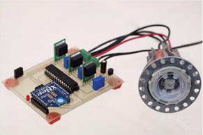
| On-board RGB LED controlled with ZigBee module. |
Off-board RGB LED luminaire controlled with ZigBee module. |
||
 |
 |
||
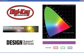
| On-board RGB LED controlled with Bluetooth module. |
Graphic interface used to control RGB LED with Bluetooth module. |
This internet connectivity allows remote control of the RGB color mixing circuit through internet accessible devices such as computers and cell phones. Since the RGB color mixing circuit relies on RS-232 communication, the ZigBee module can be replaced by a Bluetooth module provided it has a serial port profile (SPP), allowing short to medium range connectivity through various Bluetooth enabled devices.