I had an "incredibly" fun time putting this particular project together, and I hope you do too. This project shows how to build a talking clock with time & temperature display + it includes several handy C functions you may find useful for other embedded projects down the road.
I think you're only limited by your imagination with this one, but here are just a few of the fun things you can do with this project.
- Have a female voice announce the time & temperature (and pretty much anything else) every hour
- Trigger alarms based on the time or temperature
- Display OUCH as an alarm message on the SLED4C display
- Learn how to use the DS1620 with CCS C
- Learn to use the DS1307 with CCS C
- Learn how to use the EMIC text-to-speech module with CCS C
If you're a beginner with the CCS C compiler, take your time to go over the various functions. C isn't much harder to learn than BASIC, but it does take more time to get familiar with.
Although I used the PIC16F876A for this project, this code can easily be ported to another PIC, and it's quite small when compiled as-is. For the PIC16F876A this compiles to approximately 1.36 K using the CCS PCM compiler version 3.206.
If you've ever used a serial LCD, then you know how convenient they are. LCDs are great, but it's almost impossible to see an LCD display from a few feet away. If the LCD is exposed to direct sunlight or bright ambient light, forget it. This is when a 7-segment LED display really shines. The SLED4 offers the convenience of serial control with a bright and easy to see display in any lighting condition.
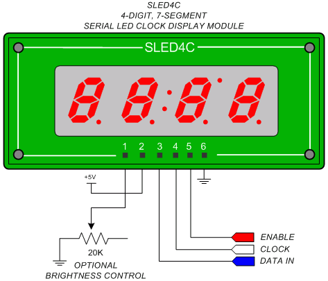
Figure#1: SLED4 Pin Diagram
The 20 K potentiometer shown above in figure #1 is optional, and may be replaced with a CDS photocell, a fixed resistor, or eliminated altogether. A photocell will react to changes in ambient lighting, and automatically dim the display in darkness, or brighten it in daylight.
If you don't need automatic display brightness control, simply leave pin #1 un-connected or use the equation below to calculate a fixed resistor value for your preferred brightness level.
The SLED4C has an onboard 10K 1% resistor to set the default display brightness to an acceptable level under most normal indoor lighting conditions. To change this, place a resistor from ground to pin #1 on the SLED4C. This will place the external resistor in parallel to the onboard 10K resistor.
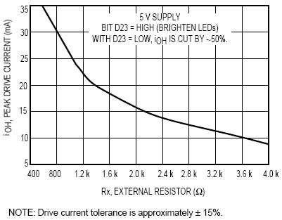
The SLED4C uses a 4-digit common cathode Super RED 7-segment display module. Care should be taken to not exceed 25mA per LED segment to avoid damaging the LED display. We recommend the use of a potentiometer or CDS photocell, but the equation below will aid in selecting a fixed value resistor if required.
Example:
To set the SLED4C peak LED segment current value to ~18mA, use a 2K 1% resistor connected between ground and pin #1 for an Rt (resistance total) value of ~1.6K.
Note: When placing an external display intensity control resistor between the display pin #1 and ground, the external resistor will be in parallel with the onboard SLED4C 10K 1% Rx resistor. The following equation may be used to determine the total parallel resistance.
Rt = Parallel resistance total
R1 = SLED4C onboard 10K 1% Rx resistor
R2 = External resistor connected between the SLED4C Rx input pin #1 and ground
Rt = R1 x R2 / R1 + R2. To set the approximate maximum current at 18mA per segment, use an external resistor value of 2K.
Rt = 10K x 2K / 10K + 2K = 20,000,000 / 12,000 = 1.6K. As shown in figure 2, 1.6K results in ~18mA peak segment drive current.
Figure#2: RX Resistor VS LED Peak Current Levels
This project shows how to use the EMIC text-to-speech module, DS1620 temperature sensor & DS1307 RTC for a digital talking time & temperature display.
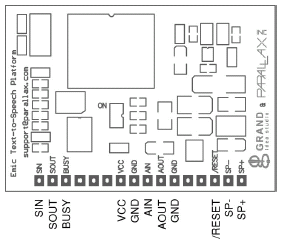
Figure#3: EMIC Text-To-Speech Module Pin-Out
Wire the PIC16F876A pin #11 labeled RSIN to the EMIC pin labeled SIN. Wire the PIC pin #12 labeled RESET to the EMIC pin labeled /RESET. We're not using any of the other EMIC pins for this project. The remainder of the circuit is shown below in Figure #4.
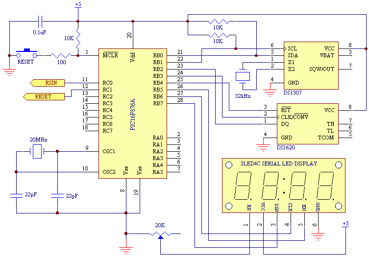
Figure#4: SLED4 Time & Date Controller Schematic
How This Stuff Works:
I recommend you download the SLED4C display datasheet located HERE and EMIC text-to-speech module docs to follow along with the explanations & C source code below. The datasheets cover a lot of additional details not shown on this project page.
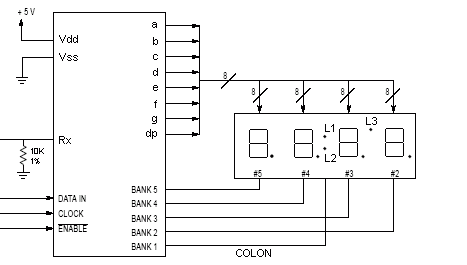
Figure#5: SLED4 LED Display Connections
As shown above in figure #5, the 4-digit common cathode LED clock display module is wired to the display controller a, b, c, d, e, f, g and dp cathode drivers. The leftmost LED digit is labeled #5. The rightmost LED digit is labeled #2. LED digits 5 through 2 are controlled by the anode "bank" drivers. The bank 1 anode driver controls the clock display colon (labeled L1 and L2), and the third upper right-hand decimal point LED labeled L3.
Writing data to the leftmost LED digit (Bank 5) requires sending code to the display register for the Bank 5 digit position. Writing data for display on the rightmost LED digit or Bank 2, we send data for Bank 2. The colon LEDs and upper right hand decimal point LED labeled L3 are turned ON or OFF by writing data to the Bank 1 register. Here's how it works.
The Configuration Register
The configuration register requires a single byte value to configure the decode mode, and control the power-down/normal power modes. The decode mode for each bank driver determines how data will be displayed on each digit of the LED display.
Example: If the display driver IC receives a hex value of $A for display on the LED digit connected to Bank 5, and Bank 5 is in HEX decode mode, then the LED connected to Bank 5 will display the capital letter A. If the display driver receives a hex value of $A for Bank 5, and Bank 5 is configured for "special decode" mode, then the LED digit connected to Bank 5 will display the special character which is the capital letter U. The chart in the datasheet HERE shows the characters for all three decode modes.
This byte sized configuration value has to be sent to the SLED4C before sending data to the display register. This configuration byte consists of 7 bits of decode mode data + 1 bit to control the display power-down or normal power mode. Refer to figure #6 below for details. Refer to the datasheet for the different decode modes, and characters associated with each mode.
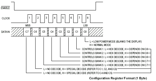
Figure#6: Display Driver Configuration Register
You will notice how the configuration byte is loaded with the correct configuration bits in the samples below. Depending on the data we want to display, we need to first configure the display to decode data for display on each bank before sending the actual data to be displayed. Look at the short example below while referring to figure #5 above.
Note: Something else you may find interesting about the power-down mode is that whatever data was displayed on the LEDs at the time you entered power-down mode, will be restored when you return to normal power mode. This is a really neat feature of the SLED4C display. It maintains the contents of the Display Register and restores the display to the same state on return to normal power mode.
The Main Code