Recent events point to the need for a simple device for testing cocktails and beers for excessive quantities of polonium. The Polonium Pen is a pocket-sized ion chamber with LED readout that is perfect for the job. Simply hold the Polonium Pen over your drink and, if the LED lights up, order something else.
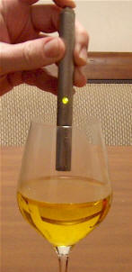
The circuit is similar to the unbalanced version of the Cheap but Sensitive Radiation Detector above and only requires two darlington transistors, an LED, and one or two resistors along with a battery, power switch and tiny homemade ion chamber. This prototype was a bit difficult to build but the pen may be built in any number of ways as long as a couple of critical requirements are met. The wire probe sticking into the ion chamber must not touch anything that is ever-so-slightly conductive, not even most glasses and the electronics must be surrounded by a metal package to shield it from stray electric fields. Because the ion chamber is so small, the LED will only light in the presence of a significant amount of radiation, most likely alpha particles. The prototype will light up brightly when held near the Americium bit in a smoke detector's ion chamber and a polonium-laced drink will easily produce the same reaction. But most radioactive sources the experimenter is likely to have will not produce any response at all, placing this in the novelty category for most of us. The LED also comes on when the button is first pressed for a couple of seconds before fading out, hence the lit LED in the photo! This "feature" insures that the pen is working properly.
The first prototype required a high-value resistor (66 megohms) across the emitter-base of the PNP darlington to get the LED to go out but the second unit didn't need one, possibly due to superior insulation of the sensor wire. A value as low as 22 megohm is fine and even lower is probably OK for detecting really "hot" drinks! But if the LED stays on with a 22 megohm, there is probably a leakage problem, either the probe's insulator or material around the transistors leads. Clean the transistor with acetone, if necessary.
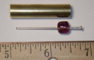
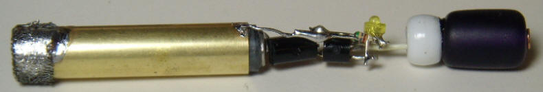
The prototype's ion chamber is made from a 1.5" long piece of 11/32" dia. brass tubing and any similar size will work. The first probe wire was a pin from one of those "pin art" bed-of-nails toys. The insulator in the photo is a glass necklace bead but it turned out to be far too conductive. It was replaced with a similar sized plastic necklace bead. The new bead was slightly too large for the brass tube but by heating the tube with a soldering iron while pressing the bead into the tube, the bead was easily cut down to size.

(Place masking tape on your fingers to prevent burns!) The bead was easily popped back out with a screwdriver. A nail was glued into the bead with a little length at the head end for making the transistor connection and then the bead was glued into the brass tube. Another bead was temporarily slipped into the other end to hold the nail in the center of the tube while the glue dried. I switched to a nail for the probe because it fit in the new plastic bead better but I recommend using a finishing nail instead of the flat head I chose. Also, tin and clean the nail before inserting in the bead, especially if steel flux is needed. Later, solder the base lead on quickly; the plastic beads melt easily. The few I tried appeared to be superb insulators.
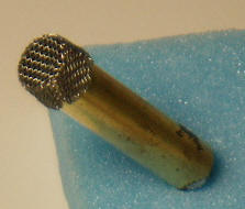
A fine mesh screen was wrapped over the open end of the chamber to keep out wind currents and electric fields. Rolling the screen between the fingers makes it conform to the shape of the tube nicely.
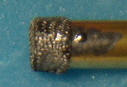
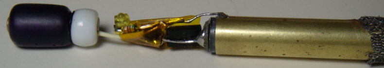
Solder the screen to the tube in one spot. Some screen materials may require steel flux but the screen should be tinned with the flux and then washed with hot water and detergent before placing it on the tube; that flux is highly corrosive! Copper screen is recommended. Make sure the sensor wire doesn't touch the screen and is fairly well centered in the tube (not critical). The circuitry was constructed using point-to-point wiring and is held in place by the base wire soldered to the nail's head and the emitter of the PNP soldered to the brass tube. One end of a battery connector was fashioned from another glass bead (long, dark tube on the right of the photo below) and a copper-plated nail. A white plastic bead was used to cover the end of the copper nail where the wire connects.
Some thin Kapton tape was carefully added to insulate the circuit from the outer tube but no tape was allowed to touch the NPN's base lead. Even electrical tape is too conductive!
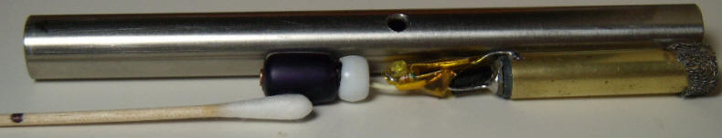
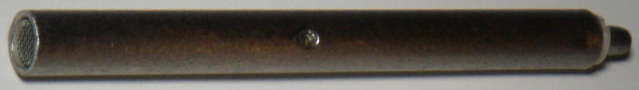
The outer tube was fashioned from 1/2" stainless steel tube but copper would have been much easier to machine. The assembly was placed next to the tube to locate the hole for the LED and a cotton swab was marked for depth with a black marker for applying epoxy to the inside of the tube to hold the glass bead battery terminal. After the epoxy was applied to the inside of the steel case, the assembly was slid into place (bead first) and the LED was positioned to face out the hole. After the epoxy set, conductive silver paint was gingerly applied to the edges of the screen to hold the ion chamber in position and to ensure a good electrical connection to the outer tube.
The other battery contact was made from a spring stolen from a AA cell battery holder fastened to a 1" steel standoff. The screw fits inside the spring and holds the narrow end of the spring to the standoff. The wide end of the spring friction fits in the steel tube to make contact. It is nicely centered by the tight fit and doesn't touch the center contact of the battery. When the button is pressed, the head of the screw makes contact with the battery's positive terminal, completing the circuit. The standoff "button" is held in place by a homemade nylon bushing that screws into the steel tube. (Threading the stainless steel was difficult!) The end of the standoff that protrudes was ground down to match the steel case. The steel case was given a coarse sanded finish, too, to hide all the scratch marks from the threading process! This isn't exactly the easy way to build such a pen but it gets the idea across.
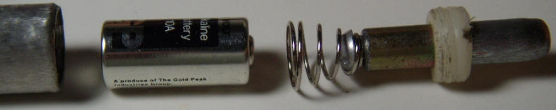
A tiny 10 A 9 Volt alkaline battery was installed and the threaded nylon bushing was tightened. A little clear epoxy fills the LED hole and the pen is complete:
Every spy and "diplomat" should have one. I wonder how much I should charge? : )