Mike Perez
Over the past few months I've been contemplating a few projects for some WRTSL54GS routers with OpenWrt,however I really need these to have a high gain antenna on the WRTSL54GS. As you may recall, this model has a fixed antenna, with no option for adding one. I decided that I needed to fix that "design flaw".
Note: By adding various antennas to this device it may become possible to violate your local or federal regulations on output power. Be careful!
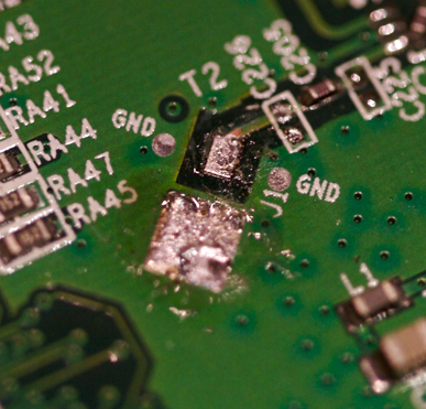
First off, we need to open the WRTSL54GS up. The screws are located under the rubber feet. Once apart, we need to de-solder the current, fixed antenna from the board. Follow the LMR cable from the antenna to the board, and de-solder both strands of the LMR from the board.
Once removed, the board should reveal two pads on which we need to solder our new connector.
Once de-soldered, we can remove the antenna from the case by pinching the end of the antenna on the inside of the connector. This will compress the size so that the outer locking ring will pass through the mount.
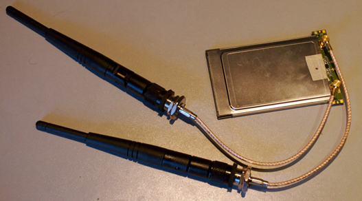
We need to make sure that we have an appropriate connector to attach a new antenna to. I happened to have scavenged parts from an old Linksys BEFSX series model. This old router had an internal PCMCIA card with two pigtails, one end with the standard RP-TNC antenna connector.
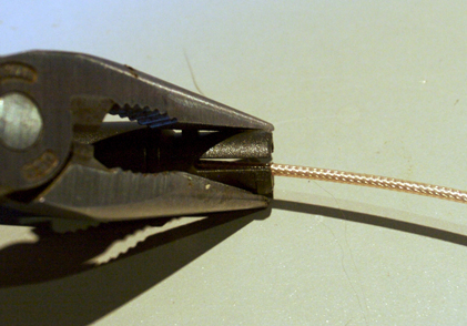
I removed the connector at the other end of the cable, as it is not important. I gave it a good pull, but certainly a pair of wire cutters will get the job done.
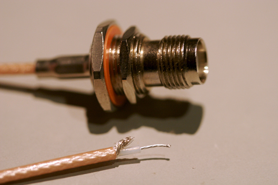
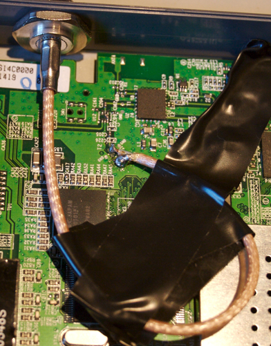
Strip the LMR cable back so that the inner and outer conductors are staggered. Match up the lengths that you need with the two pads to verify your length - the smaller inner conductor will be attached to the smaller pad on the board, while the outer conductor will be attached to the larger pad. Don't solder them together! This will create a short, and render your antenna inoperable, possibly even frying your router!
We also need to modify the case so that the external portion of the connector will fit through. My connector at the base was 3/4 of an inch, so I drilled a 3/4 inch hole into the edge of the case, right near the original connector.
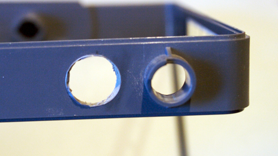
Part of the selection of this location was so that it would still be at the top of the unit, and the board has a notch out of it at this location. The notch leaves a handy place to be able to fit the additional portion of the connector between the board and the edge of the case.
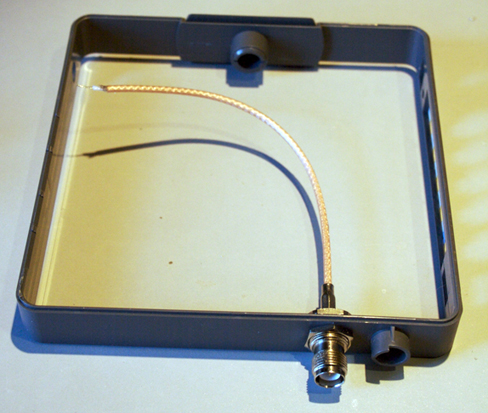
Once mounted, solder the LMR form our new connector to the board as described earlier. I utilized some electrical tape to maintain the bend in the LMR and to hold it down to the board. This allows me to have both hands free to solder!
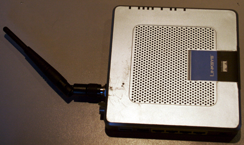
Once complete we can reassemble our router and show off our new connector.
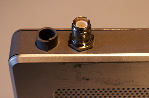
One of the nice features of using the RP-TNC connector is that we can reuse antennas from most of our other Linksys devices!
Have fun adding new antennas!