Lawrence Mayes
EDN
In audio-mixing applications, one frequently required function involves mixing a monaural or single-channel source into a stereo-sound field. Audio engineers refer to a panoramic-potentiometer circuit as a circuit that generates left and right signals of correct amplitudes from a monaural signal and places the signal's image anywhere in a stereo-sound field. For the image's loudness to appear independent of its final position, the derived left and right signals must add to produce a constant-power signal rather than a constant-voltage signal.
 |
||
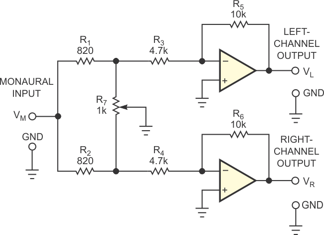
| Figure 1. | In this basic panoramic-potentiometer circuit, the position of R7’s wiper controls the position of a monaural image in a stereo audio signal. |
|
The widely used circuit in Figure 1 performs this function by dividing the monaural signal between the two stereo channels and varying each channel's gain between zero and M such that at R7's centered position, each channel's gain is 0.707M. If you calculate component values to achieve these conditions, then the circuit presents the remarkable property that, for all positions of R7's wiper, the sum of the powers in the left and right channels is constant to within 0.19 dB.
 |
||
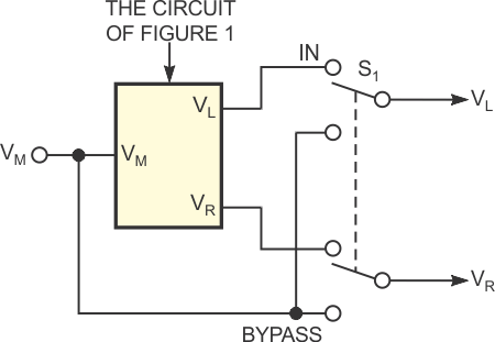
| Figure 2. | A DPDT switch removes the panoramic potentiometer but introduces wiring complexity and transients. |
|
 |
||
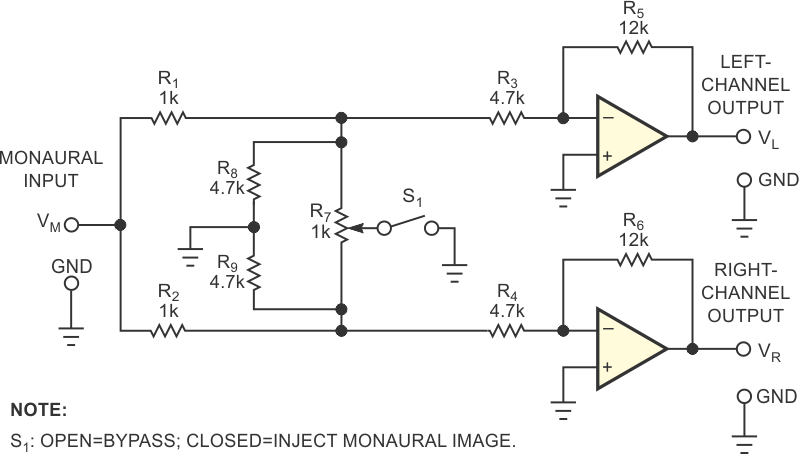
| Figure 3. | Adding resistors R7 and R8 and SPST switch S1 simplifies wiring and minimizes transients. | |
You can use a DPDT switch, S1, to bypass the circuit and thus remove it from the audio chain (Figure 2). As an alternative, you can add two resistors and use an SPST switch to disable or enable the circuit. The circuit in Figure 3 presents the same gain characteristics as in Figure 1. Closing switch S1 enables the panoramic-potentiometer function, and opening the switch produces a fixed central-sound image. Additionally, from a practical viewpoint, the circuit of Figure 3 simplifies wiring and introduces no significant switching transient because enabling the panoramic-potentiometer function involves only grounding R7's wiper. Even when you use preferred-value components and disregard component tolerances, the circuit introduces a maximum gain error of only 0.21 dB.