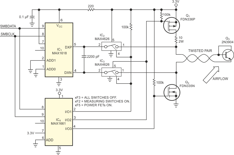
As higher levels of power dissipation underscore the need for cooling, more and more fans are finding their way into small electronic enclosures. The dust that fans pull into these enclosures can, however, cause major problems for high-reliability systems. By coating heat sinks and electrically charged components, the dust acts as a blanket that raises the effective thermal impedance between the components and the air. A simple way to combat this problem is to place a disposable filter on the air intake. If you fail to replace the filter on a regular basis, however, it can become clogged and act as an air dam, a condition that is worse than the original problem. Trying to sense a clogged filter by sensing the fan's rotation with tachometer signals is useless, because fan rotation is not directly related to airflow. You can detect poor filter maintenance by determining the actual airflow with a "hot-wire" anemometer, but most electronic anemometers are costly and bulky. As an alternative, you can create an SMBus/I2C anemometer using an I/O expander, a few inexpensive switches, and a low-cost remote-temperature sensor (Figure 1).
 |
||
| Figure 1. | This anemometer measures airflow by heating Q3 and then noting the time for Q3 to return to its original temperature. |
|
Use the SMBus I/O expander, IC4, to turn off MOSFETs Q1 and Q2 and to turn on the analog switches IC2 and IC3. Measure the ambient air temperature with no preheating of Q3. Then, to apply current for heating Q3, turn off IC2 and IC3 and turn on Q1 and Q2. Allow an approximate five-minute "soak" to reach temperature equilibrium. (The exact heating time necessary for equilibrium depends on the setup; you must determine it by experiment.) At equilibrium, remove power from Q3 by turning off Q1 and Q2, and turn on analog switches IC2 and IC3 to make temperature measurements. Airflow directly relates to the rate at which the temperature drops; you can determine it by noting the time required for the transistor to return to within 1° of its original temperature. The temperature sensor injects a small current into the base junction, so careful layout is important to keep noise off the DXP and DXN lines.
| Table 1. | Fan Voltage Versus Cooling Time | ||||||||||
|
|||||||||||
If you mount the remote transistor in an air channel, the use of twisted-pair wire allows distances to 12 ft. Table 1 shows fan voltage (airflow) versus cooling time for a sensor placed approximately 12 in. away from a fan running at full speed (12 V), medium speed (8 V), low speed (6 V), and zero speed. Soak times as long as 30 minutes do not significantly alter the times. The circuit draws approximately 200 mA when Q3 is heating. If this power dissipation poses a problem, you can lower the measurement frequency to hourly or even daily cycles, because changes in airflow occur slowly over time. You can also schedule the measurements during times of low system activity, when overall power use is low.
Materials on the topic
Application. Teams I2C
| I2C instructions | |
| Write to MAX1661 (address = 40h): | |
| F3h F2h | Turn off all switches; Then turn on measurement switches |
| Write to MAX1618 (address = 30h): | |
| 09h 48h | Write Configure; One shot mode |
| 0Fh | Write one shot command |
| W 01 R ??h | Read ambient temperature |
| Write to MAX 1661 | |
| F3h F5h | Turn off all switches; Then turn on power FETs |
| Soak for 5 minutes | |
| Write to MAX1661 | |
| F3h F2h | Turn off all switches; Then turn on measurement switches |
| Write to MAX1618 | |
| 0Fh | Write one shot command |
| W 01 R ??h | Read temperature |