There have been many different ideas presented for increasing the acoustic output of a piezo buzzer or ultrasonic transducer. Most of them involve rather complicated circuitry that drives up the total solution cost; such as boosting the low-voltage logic power supply to a higher voltage or using an H-bridge topology.
In contrast, this Design Idea shows how the acoustic output of a piezoelectric transducer can be increased while minimizing the parts count and cost. Before we look at the new approach, let's look at some of the most commonly-used piezo-acoustic designs and their drawbacks.
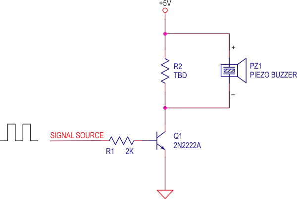
The simplest piezo drive circuit consists of a transducer and a switching transistor (Figure 1). The voltage across the transducer cannot be greater than the supply voltage, which places an upper limit on the acoustic output. The resistor R2 serves to discharge the capacitance of the transducer. The RC time constant should be short relative to the period of the resonant frequency of the transducer. Low resistor values decrease electrical efficiency while damping the mechanical (acoustical) resonance of the transducer, which of course reduces the acoustic efficiency.
 |
||
| Figure 1. | While this piezo drive circuit is simple, it is very inefficient. | |
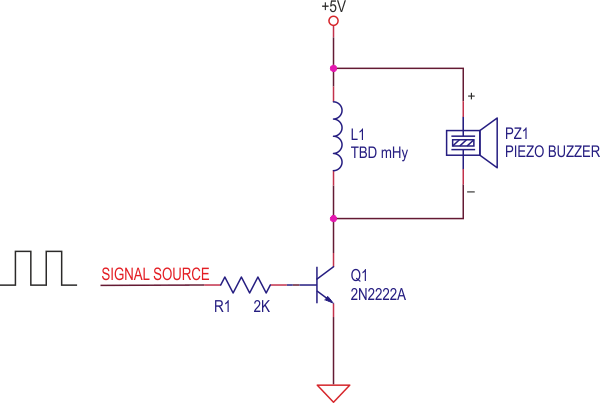
A common enhancement to this circuit replaces R2 with an inductor as shown in Figure 2.
 |
||
| Figure 2. | Substituting an inductor for R2 improves the piezo driver’s output and efficiency. |
|
Often the inductance value is selected to electrically resonate with the capacitance of the transducer (buzzer) at the acoustic resonance of the transducer. This approach can provide more acoustic output than the parallel resistor approach, but there is still a lot of room for improvement. At best, the peak-to-peak voltage across the transducer may reach 40 Vppk, while 20 Vppk is more typical with a 5 V power supply.
That’s because the transistor collector-base junction is forward biased on the negative swing of the parallel resonant circuit formed by the inductor and transducer capacitance, which clamps the voltage swing, limiting acoustic output.
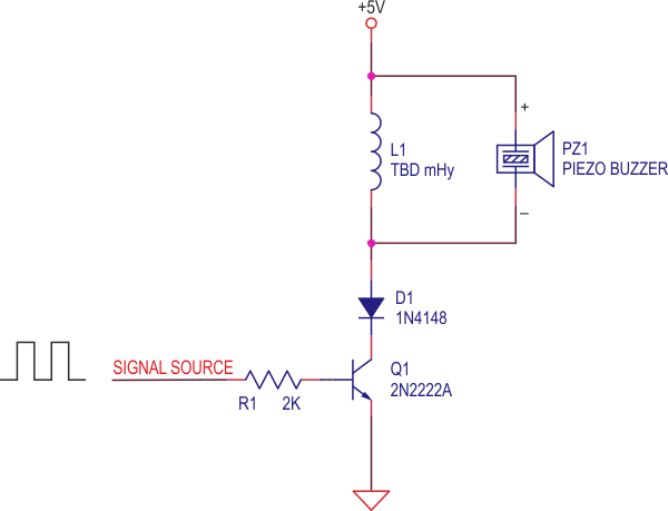
Adding a diode decouples the C-E junction (or if a FET is used, the body diode junction) from this negative swing, providing a much larger voltage swing across the transducer, increasing the acoustic output (Figure 3). Although the forward voltage of the diode does reduce the applied power supply voltage, the increased resonance voltage more than makes up for this small loss.
 |
||
| Figure 3. | Using a diode can eliminate the circuit's negative swing. | |
To achieve any further improvements, we need to consider that there are actually two resonances at work in this small system:
- Acoustic resonance of the transducer, mechanical and cavity resonances apply
- Electrical resonance of the inductance and transducer capacitance
The electrical resonance frequency need not be the same as that of the acoustic resonance. In fact, if it is roughly 2× the acoustic resonance, the peak voltage across the transducer can be greatly increased.
 |
||
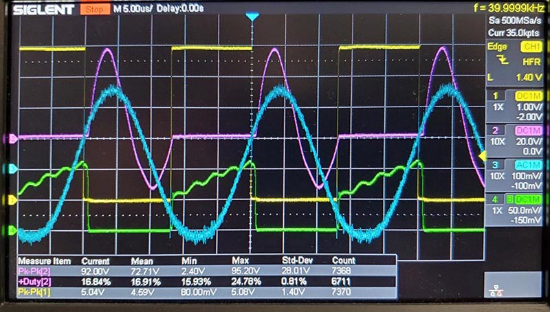
| Figure 4. | Here is how the circuit behaves in real life. | |
This is demonstrated in Figure 4, where the waveforms are derived using the following circuit parameters:
- Power supply = 5 VDC
- L1 = 3.2 mH
- C(piezo) = 2 nF
- Signal source frequency = PZ1, resonant frequency = 40 kHz
- Signal source duty cycle is adjusted to eliminate a large current spike on turn-on
Note that item #5 identifies a potential problem lurking within this new solution that must be addressed. If the signal source can turn on the transistor after the transducer voltage goes positive, there will be a large narrow current spike, which can reduce electrical efficiency and potentially degrade the transistor over time. Increasing the duty cycle to cause transistor turn-on while the resonant voltage is slightly negative eliminates this spike.
With all that sorted out, let's look at how our circuit behaves in real life using our handy four-trace smart oscilloscope:
- Yellow = drive voltage, ~48% duty cycle, 5 Vppk. at 40 kHz
- Violet = electrical resonance voltage across the transducer, 92 Vppk. at 80 kHz
- Green = transistor emitter current, ~80 mA peak at 40 kHz
- Blue = acoustic output of the transducer, measured with a MEMS mic
The high peak voltage across the transducer is achieved by using a smaller inductor than one which would resonate at 40 kHz, allowing current to rise about twice as fast, in this example, providing twice the current to “charge” the inductor’s magnetic field.
The peak voltage is analogous to pushing a swing, where the higher the peak voltage available, the harder the push that's delivered. In this system, this translates to a larger displacement of the transducer surface, resulting in greater acoustic output.
This Design Idea is not meant to be an exhaustive treatise on resonant circuits. Instead, it demonstrates a procedure by which any resonant piezoelectric transducer or buzzer can be driven to high acoustic output with a very simple, low-cost circuit.
The procedure can be summarized like this:
- Determine the acoustic resonant frequency of the transducer
- Create a drive pulse train at that same frequency, starting at a 50% duty cycle
- Tune the duty cycle to eliminate current spikes at turn-on as needed
- Determine the capacitance value of the transducer
- Choose an inductance value that will electrically resonate at approximately double the acoustic resonance.
It can be difficult to duplicate the acoustic/electrical circuit presented here in simulation, since the transducer consists of two or more potential resonant elements. These include the mechanical resonance of the transducer element, the acoustic resonance of the transducer enclosure (reference Helmholtz resonance), and of course the electrical resonance of the transducer capacitance with the external inductance.
The acoustic loading by radiation from the transducer port or diaphragm adds yet another difficulty to simulation. A simple electrical simulation of this circuit produced 240 Vppk across the transducer, which is more than double that created in the real circuit. Acoustic loading may represent the majority of losses that reduce peak transducer voltage in this system, compared to the simulated results.
By using this simple procedure, one can easily maximize transducer output with minimal time and effort.