When a processor-controlled device must operate reliably, designers often choose to periodically reset the processor rather than rely on a watchdog configuration. In low-power systems, this periodic-reset circuit can consume a large part of the system's current budget or may fail to operate at low voltages.
The circuit in Figure 1 generates a low-going reset pulse of 100-µsec duration. The circuit consumes less than 1-µA operating current and operates from 1.8 to 5 V supplies with little variation in the output period. The circuit is an adaptation of a normal relaxation oscillator. The circuit has a differentiator and diode clamp on the output to generate the 100-µsec low-going pulse. You can adjust the period of the output waveform by varying R1, C1, or both. You can adjust the pulse width of the low-going reset pulse by varying RP, CP, or both, or you can change the polarity by repositioning D1.
 |
||
| Figure 1. | This reset circuit consumes less than 1 µA and delivers a 100-µsec- wide reset pulse every 1.3 sec. |
|
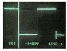
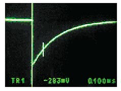
Figure 2a shows the comparator's output waveform, which has a period of approximately 1.3 sec. The period varies from 1.308 sec with a 4.5 V supply to 1.306 sec with a 1.8 V supply. Figure 2b shows details of the low-going reset pulse, which takes the shape of the output of a normal relaxation oscillator. The reset pulse is 100 µsec wide at its 30% point on the exponential curve.
|
||||
| Figure 2. | The comparator in Figure 1 produces a square wave with a period of 1.3 sec (a); the output differentiator yields a low-going pulse of 100-µsec width at its 30% point (b). |
|||
The 350-nA supply current, the 1.8 to 5.5 V supply range, and the SOT-23 package make the MAX919 ideal for this application. Measurements for the circuit reveal lower than 1-µA operating current. This low consumption would allow the circuit to operate from a single AA lithium cell for 250 years. With judicious component choice, the circuit can generate periods from milliseconds to minutes. To ensure good temperature stability, you should use metal-film types for R1 and RP and NP0 types for C1 and CP. Assuming a reset-logic threshold of 30% of the supply rail, you can use the following formulas to adjust the output pulse width and period: pulse width ≈ 0.36RP CP, and period ≈ 0.4R1 C1.