Introduction
When you use microcontrollers in your designs, sometime you face a problem how to show user required data. Several LEDs, 7 segment display or LCD module can be solution. But if you must show a lot of information simultaneously, it can be difficulty. Large LCD modules are expensive and graphic modules require complicated control. You can solve it with a help of PC. Just send data via serial line to the computer and display everything on computer's display. But another user usually occupies computer or you need it for another job ... :-)
I have had to solve the same problem some time ago. I have chosen normal small TV set for that. A lot of families change TV in this time because of digital broadcasting or modern flat and slim LCD and plasma displays. So they put older TV set away and it is dormant somewhere. Or you can buy older TV very cheap.
Aim of construction
The display unit must be maximum easy. For data displaying is text mode with semigraphic mode sufficient. Just only 1 integrated circuit - microcontroller - must guarantee every function of the unit. A keyboard will be useful for data input.
"Button by button" assembling of keyboard is complicated and mechanical design is a weak point in hobby construction. Special keyboards are usually inaccessible or expensive. That's why I have chosen standard IBM PC keyboard. PC keyboard solves as design as character variability - there are all characters on keyboard. Economic view is very advantageous and accessibility is almost unbeatable. The size is disadvantage of PC keyboard but beside TV set it doesn't matter.
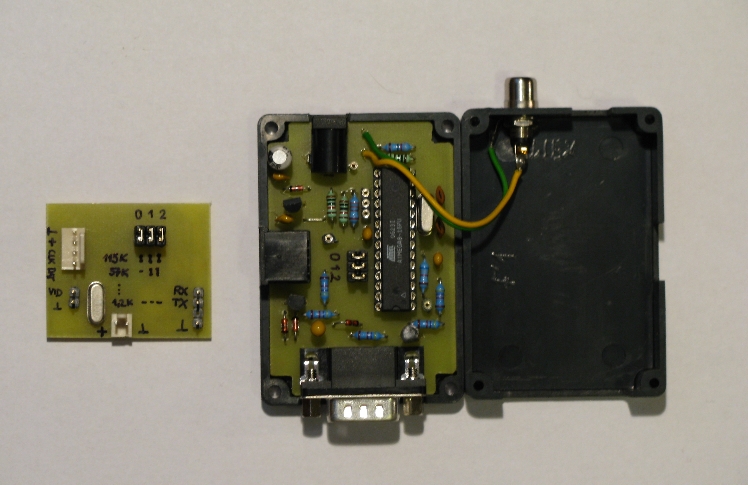
I have developed 2 versions of TV terminal. "Built-in" version is designed for utilization in device. The second version is standalone device with external power source.
The described TV terminal accomplishes these results:
- Display mode: black and white
- Text mode: 40 characters x 25 lines
- Semigraphic mode: 80 × 75 "points"
- Printable characters: ASCII 32 - 127
- Keyboard: IBM PC AT compatible
- Control characters: 11
- Serial line speeds: 1200 Bd to 115.2 kBd
- Power supply: 9 - 12 V or 5 V (built-in version)
- Current consumption: cca 30 mA + keyboard consumption
Wiring diagram
TV terminal utilization is very easy. Connect video output to video (AV) input on TV set. Set communication speed on J1 jumpers. You can connect PC keyboard but it isn't necessary. Turn terminal ON and display will show current parameters. The terminal is in full operation 3 seconds later.
Schematic wiring is similar for both versions. You can find differences in the power supply part and in the serial line interface. Standalone version has got voltage regulator and simple RS232 to TTL converter. I have used only 2 transistors for logic voltage converter. Integrated circuit takes much more space.
As you can see wiring diagram is very easy. Most of the functions are centred in the microcontroller U1. There must be minimally 1 kB RWM for 40×25 character screen. I have selected well-known and available type - ATmega8.
The U1 microcontroller has to maintain 3 independent processes:
- Video signal generation.
- Character reception from the keyboard, decoding and dispatch to serial line.
- Receiving characters from serial line and storing it in the memory.
Independency for every of these 3 processes was the most complicated task. Video signal must be generated utterly on the dot. Program was created in assembler and compiled code is here.
Microcontroller clock is on maximum frequency - 20 MHz. Frequency 22 MHz would be better, but for reproducibility I accepted 20 MHz. This backtracking brings slight differences in the horizontal width of pixels. Forgive me - it is only hobby design (or maybe you will notice this never :-).
The power supply voltage regulator and logic level converter are included in the standalone version. To keep circuit easy I selected (inspired by biprog) simple converter with 2 transistors. There is no problem with short serial line. But if you connect long wires with bigger capacity then communication can produce errors in higher speeds. Be careful with used keyboard. Consumption most of them is reasonable low, but there are types with consumption above 100 mA. High current causes overheating of U2 voltage regulator. Use voltage regulator 7805 in the TO220 case or reduce power supply voltage in this event.
Setting in operation
It is very easy to make both versions of TV terminal. Mount and solder every component to PC board. Check up complete device. The last operation is downloading program into microcontroller. Set fuses: RESET=ON, BROWN-OUT LEVEL 4.0V, OSCILLATOR=EXT. CRYSTAL HIGH FREQ.
Properly programmed microcontroller with running oscillator will produce video signal. Change slightly value of R7 when TV doesn't synchronize.
Connect built-in version directly to other microcontroller. Logic levels respond standard convention (log. "1" = 5 V). I suggest connecting serial line input and output for the first test. Type text on keyboard and check TV screen.
Component bil list
|
Standalone version - classic parts |
|||
|
Component |
Value / type |
Pieces |
Notice |
|
U1 |
ATMEGA8-16 |
1 |
DIL28 case |
|
U2 |
1 |
stabilizer 5 V |
|
|
T1 |
1 |
or similar NPN |
|
|
T2 |
1 |
or similar PNP |
|
|
XT1 |
20 MHz |
1 |
crystal |
|
D1,D2,D4 |
1 |
- |
|
|
D3 |
1 |
- |
|
|
C1,C2 |
15 pF |
2 |
ceramic |
|
C3 |
10u/16 |
1 |
elektrolytic or tantalum |
|
C4 |
100u/16 |
1 |
elektrolytic or tantalum |
|
C5-C8 |
100n |
4 |
ceramic |
|
R1-R5 |
4K7 |
5 |
miniature e.g. R0207 |
|
R6,R10,R11 |
10K |
1 |
miniature e.g. R0207 |
|
R7 |
1K0 |
1 |
miniature e.g. R0207 |
|
R8 |
82R |
1 |
miniature e.g. R0207 |
|
R9 |
330R |
1 |
miniature e.g. R0207 |
|
CN1 |
CANON 9 MALE |
1 |
for the PCB |
|
CN2 |
NAZ 2.5 |
1 |
Power connector 2.5 for PCB |
|
CN3 |
CINCH FEMALE |
1 |
wall mount |
|
CN4 |
Mini DIN6 FEMALE |
1 |
(PS2) for PCB |
|
J1 |
JUMPER |
3×2 |
Jumpers and pins |
|
Built-in version - SMD components |
|||
|
Component |
Value / type |
Pieces |
Notice |
|
U1 |
ATMEGA8-16 |
1 |
TQFP32 case |
|
XT1 |
20 MHz |
1 |
crystal |
|
C1,C2 |
15 pF |
2 |
ceramic 0805 |
|
C3,C4 |
100 nF |
2 |
ceramic 0805 |
|
C5 |
10u/10 |
1 |
tantalum SMD |
|
R1,R2 |
do 47R |
2 |
1206 (maybe short-circuit) |
|
R3 |
1K0 |
1 |
0805 |
|
R4 |
82R |
1 |
0805 |
|
R5 |
100R + 220R |
1+1 |
1206 |
|
R6,R7 |
10K |
2 |
1206 a 0805 |
|
R8 |
4K7 |
1 |
1206 |
|
J1 |
JUMPER |
3×2 |
Jumpers and pins |
|
- |
I/O pins |
- |
you can choose |
Click on the picture for 600 dpi picture (save it and print)
PCB for built-in (SMD) version
Application of TV terminal
TV terminal responds to 3 character types:
- Control characters (11 selected characters)
- Printable ASCII characters 32 - 127
- Semigraphic characters 128 - 191
All remaining control characters (21) are displayed as a square. Characters 192 - 255 are ignored. Active control characters are in the table. To tell the truth, I have modified function for control characters SOH, STX, DC1,... DC4. Emulation e.g. VT100 terminal is to no effect for such easy device. Terminal control is easier and quicker with this reduction. Default "new line" is achieved by CR+LF.
|
Character |
Decimal |
Hexadecimal |
Description |
|
SOH |
1 |
0×01 |
Set mode "CR or LF for new line" (Unix, Apple like) |
|
STX |
2 |
0×02 |
Set mode "CR and LF for new line" (Microsoft like) |
|
BS |
8 |
0×08 |
Backspace |
|
TAB |
9 |
0×09 |
Horizontal TAB - move cursor to position modulo 8 |
|
LF |
10 |
0×0A |
Line feed (see SOH and STX as well) |
|
FF |
12 |
0×0C |
Form feed (clear screen) |
|
CR |
13 |
0×0D |
Carriage return (see SOH and STX as well) |
|
DC1 |
17 |
0×11 |
Cursor ON |
|
DC2 |
18 |
0×12 |
Cursor OFF |
|
DC3 |
19 |
0×13 |
Next byte will specify X position of cursor |
|
DC4 |
20 |
0×14 |
Next byte will specify Y position of cursor |
Cursor positions start in the upper left corner. Upper left corner is 0,0 - bottom right corner is 39,24. Semigraphic characters are split into 6 squares. Semigraphic code is explained in the picture.
IBM PC AT compatible keyboard can be connected to terminal. You can use both keyboard types - with PS2 connector or original DIN5. Standalone version is ready for PS2 connector. Use DIN5/PS2 reduction for keyboard with old DIN5 connector.
You can type printable characters directly. Special characters (e.g. control characters or characters above 127) can be placed as well. Left ALT must be pressed at first and then 2 hexadecimal characters follow. E.g.: for LF character press successively keys "left ALT" + "0" + "A". This way you can place all characters 0 to 255.
Special keyboard mode is remnant from the development time. When you press F12 key then keyboard is switched into "SCAN mode". Pressing of key will produce text string with base SCAN code of the key. E.g. press keys "A" and "B" - terminal will send text string "1C 32 ". Key F12 stops this mode as well.
There must be the same speed on the both devices for the proper communication. Serial line speed is conditioned through JUMPERs J1-0, J1-1 and J1-2 (see table). Communication is 8 bit always. Communication parameters are displayed for about 3 seconds on the screen after the start.
|
Speed |
J1 - 2 |
J1 - 1 |
J1 - 0 |
|
115200 Bd |
ON |
ON |
ON |
|
57600 Bd |
ON |
ON |
OFF |
|
38400 Bd |
ON |
OFF |
ON |
|
19200 Bd |
ON |
OFF |
OFF |
|
9600 Bd |
OFF |
ON |
ON |
|
4800 Bd |
OFF |
ON |
OFF |
|
2400 Bd |
OFF |
OFF |
ON |
|
1200 Bd |
OFF |
OFF |
OFF |
Conclusion
This TV terminal is very easy device. Even a beginner should assemble it without problems. TV terminal is practical for your microcontroller-controlled device. Most of modern microcontrollers have built-in universal serial unit. So you can design user interface very easy with TV terminal and few line code in your microcontroller.
TV terminal is advantageous for:
- device with a lot of displayed information,
- debugging phase of design (I work on the PC and TV terminal is interface for debugged microcontroller),
- to make keyboard and display for occasionally gadget is waste of time.