Some sports enthusiasts want to know altitude changes from an initial elevation. A small, lightweight, portable altimeter is easy to design using modern micromachined pressure transducers. Inverting barometric pressure and compensating for nonlinearities in air-pressure changes with respect to altitude produces a reasonably accurate altimeter.
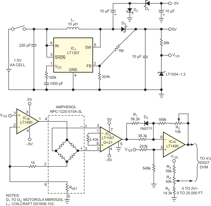
Figure 1 shows a small, handheld altimeter based on a micromachined pressure transducer. The circuit takes advantage of the inverse relationship between air pressure and altitude. The aim of this circuit is to be small, lightweight, and portable. Accuracy is not paramount; errors as high as 3%, such as a 300-ft error at 10,000-ft altitude, are acceptable. The speed of the circuit is also not critical: Extreme changes in altitude in milliseconds may prove fatal to whoever is attempting to read the output.
 |
||
| Figure 1. | To produce a reasonably accurate altimeter, conditioning circuitry inverts the barometric pressure of a micromachined pressure transducer and compensates for nonlinearities in air-pressure changes with respect to altitude. |
|
The heart of the altimeter is an NPC-1220-015-A-3L pressure transducer. This 5-kΩ bridge provides 0 to 50 mV of output voltage for a 0- to 15-psi pressure range. To power the transducer and signal-conditioning circuitry, a micropower dc/dc converter, IC1, generates 5 V from a single AA battery, and a charge pump generates a –5 V supply.
The output of the transducer drives an instrumentation amplifier, IC2, which provides an initial gain of 21. A nonlinear gain stage comprising IC3B and associated components then inverts the output of the instrumentation to provide a voltage that is inversely proportional to air pressure. D4 and R1 introduce the nonlinear gain, and the final output is directly proportional to altitude.
R2 performs gain calibration in the signal-conditioning circuitry. This potentiometer calibrates out any normal variations in part tolerances and sets the altimeter for a 100-mV change in output for every 1000 ft of altitude. The circuit has some initial offset, as well as an offset that is determined by barometric- pressure variations. You can use R3 to R5 to null this offset, giving a 0 to 1 V output for 0 to 10,000 ft of altitude.
Altimeter testing was performed using a de Havilland DHC-6 Twin Otter for an ascent to 13,000 ft, followed by free descent – limited by the engineer's parasitic drag – to 3000 ft. Subsequent deployment of an aerodynamic decelerator (Precision Aerodynamics Icarus Omega 190) prevented engineer injury or circuit damage. Aircraft rental for testing is available at many local airports. Extensive instruction in free descent and the use of aerodynamic decelerators are highly recommended before undertaking testing of this nature.