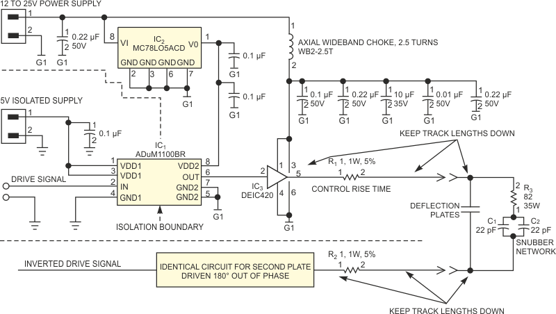
The circuit in Figure 1 provides a 20-MHz square wave across a set of highly capacitive ion-deflection plates in an experimental instrument. To get the required deflection, the plate voltage must be 20 to 30 V, much higher voltage than conventional logic or driver families can provide. To minimize artifacts, the rise and fall times must be very fast, with a minimum of overshoot and ringing. Identical circuits, phased 180° apart, drive the plates. The driver uses a IXYS DEIC420 high-speed MOSFET gate driver to drive a 1000-pF capacitive load from 0 to 25 V in less than 5 nsec. With smaller loads of a few hundred picofarads, the rise time decreases to approximately 3 nsec. Series resistors R1 and R2 control the output rise and fall times, allowing you to trade off the rise and fall times against overshoot and ringing.
 |
||
| Figure 1. | You can use a high-speed, MOSFET-driver IC to drive ion-deflection plates. | |
A high-speed Analog Devices ADuM1100BR ferromagnetic signal isolator prevents system ground loops by providing dielectric isolation for the input signal; you could also use high-speed optocouplers. A low-power MC78L05CD regulator provides power for the signal-isolator output stage.
A snubber network, composed of a thin-film, high-power resistor R3 in a TO-220 package and high-quality NP0 capacitors C1 and C2, terminates the load at the plates. You empirically determine snubber values by observing the radiated field on an RF spectrum analyzer using a passive RF probe. You “tune” the snubber network to reduce higher order signal harmonics. Note that placing an oscilloscope probe on the outputs significantly increases the observed higher order harmonics, indicating that adding the probe to the circuit increases ringing and overshoot. The DEIC420 is mounted in a high-speed, high-power package that minimizes lead inductance. The part requires multiple bypass capacitors at each of its power pins. You should choose the capacitors so that their self-resonant frequencies do not significantly overlap. Having a full ground plane and using high-speed and RF-signal-layout techniques are critical to the proper operation of this circuit. The input must be well-isolated from the output. Double-pulsing, ringing, and even oscillation may occur if you don't strictly follow these practices. The tracks or cabling between the driver and the load should be impedance-controlled and should be as short as possible. The DEIC420 requires good heat-sinking when you operate it at high speeds and high voltages. When operating at 20 MHz from a 25 V supply, the two drivers and snubber together dissipate 130 W.