Introduction
LCD character displays can be found in espresso machines, laser printers, children's toys and maybe even the odd toaster. The Hitachi HD44780 controller has become an industry standard for these types of displays. This tutorial will teach you the basics of interfacing with a HD44780 compatible display using some DIP switches and a few other components.
Pinout
The module that we are using is a 16 character x 2 line display that we stock over here. It uses an ST7065C controller, which is HD44780 compatible. The figure below shows the LCD module and pinout.
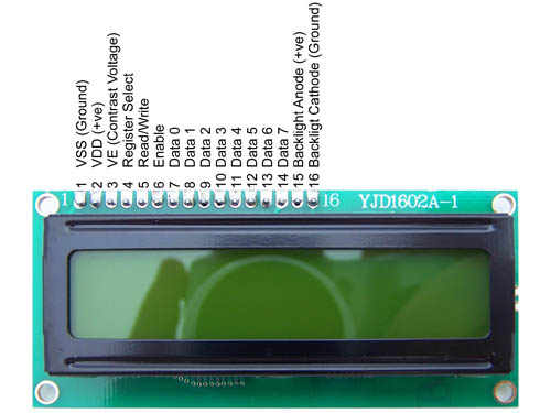
The last 2 pins (15 & 16) are optional and are only used if the display has a backlight.
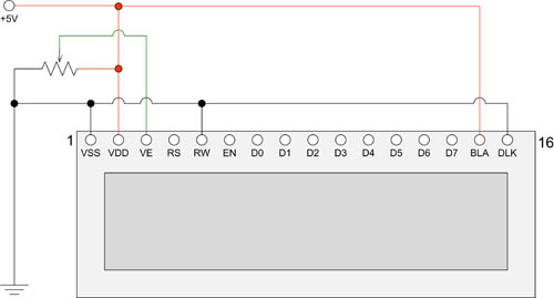
The circuit diagram below shows the LCD module with the basic "plumbing" wired up. You will notice that pin 5 (RW) is tied to ground. This pin is use to control whether you are reading or writing to the display. Since reading from the display is very rare, most people just tie this pin to ground.
The potentiometer connected to pin 3 controls the LCD contrast.
Sending Data and Commands
Data and commands are sent to the module using the 8 data lines (pins 7-14) and the RS line (pin 4). The RS lines tells the module whether the 8 data bits relate to data or a command. The data/command is read on the falling edge of the enable line (pin 6). This means that when enable transitions from high to low, the values of D0 to D7 and RS are read.
So to send data or a command to the display, you need to
- Set Enable to high
- Set RS and D0-D7 desired values
- Set Enable to low
There are minimum wait times between these operations, but I won't go into them here. You can look these up in the LCD Module Datasheet. (look at the timing diagrams on page 4)
HD44780 based display modules also have a 4 bit interface mode. Under this mode the data or command is transferred to the module using 2, 4 bit nibbles. This will be discussed in more detail below.
Instructions and Characters
The tables below show the instruction set and character table. Click on a table to get a larger view.
 Click to enlarge |
 Click to enlarge |
Assembling the Circuit
Normally you would drive an LCD display from a microcontroller, computer or similar device. For this exercise we will use just a series of switches. This cuts the interface to the absolute bare essentials.
The circuit being built is shown below.
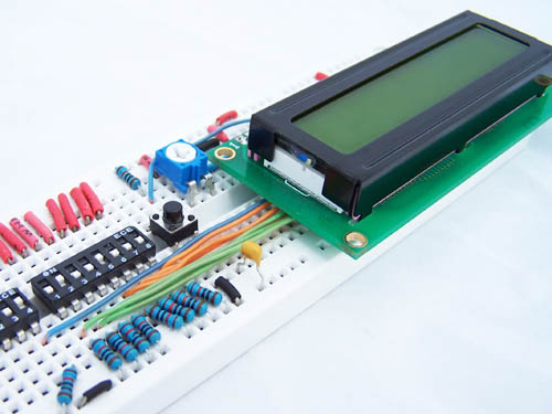
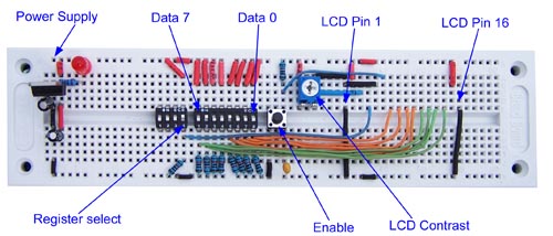
The photo below shows the circuit, on a breadboard without the LCD module. I've also added a small L7805 based power supply on the right hand side of the board. You can get the parts for the power supply here.
The Register Select and data lines are pulled down using a 10K resistor and when the dip switch is closed, those lines go high. The enable line on the other hand is pulled high and when the button is pressed, the line goes to ground. The enable button has a 10nF capacitor to de-bounce it.
Before inserting the LCD module into the breadboard, you will need to solder a row of 16 pin single row headers. This is shown in the photo below.
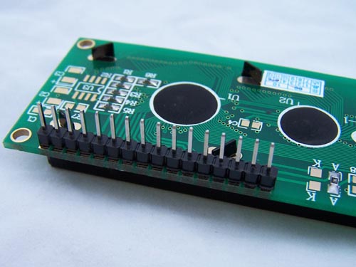
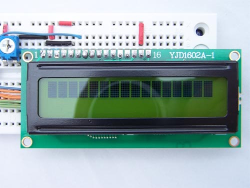
Next we insert the LCD module into the breadboard and power it on. When you insert the module into the breadboard, you need to be gentle and work the pins in slowly because the pins are a bit thicker than you would normally use with a breadboard.
If you don't see the pattern shown below, you will need to turn the contrast pot till you do. This pattern is the default pattern for an uninitialized LCD display.
Interfacing via the 8 bit mode
To interface to the display and output text we need to
- Initialise the display,
- Set entry mode, and
- Send a sequence of characters to display
So to output the text "Hello World" we need to power up the device then enter the following sequence of Data/Commands, pressing Enable at the end of each Data/Command block.
|
RS |
D7 to D0 |
Description |
|
0 |
0 0 1 1 - 1 0 0 0 |
Function set, 8 bit, 2 lines, 5×7 |
|
0 |
0 0 0 0 - 1 1 1 1 |
Display ON, Cursor On, Cursor Blinking |
|
0 |
0 0 0 0 - 0 1 1 0 |
Entry Mode, Increment cursor position, No display shift |
|
1 |
0 1 0 0 - 1 0 0 0 |
H |
|
1 |
0 1 1 0 - 0 1 0 1 |
e |
|
1 |
0 1 1 0 - 1 1 0 0 |
l |
|
1 |
0 1 1 0 - 1 1 0 0 |
l |
|
1 |
0 1 1 0 - 1 1 1 1 |
o |
|
1 |
0 0 1 0 - 0 0 0 0 |
space |
|
1 |
0 1 0 1 - 0 1 1 1 |
w |
|
1 |
0 1 1 0 - 1 1 1 1 |
o |
|
1 |
0 1 1 1 - 0 0 1 0 |
r |
|
1 |
0 1 1 0 - 1 1 0 0 |
l |
|
1 |
0 1 1 0 - 0 1 0 0 |
d |
Interfacing via the 4 bit mode
The main benefit of the 4 bit mode is that less data lines are required. In this mode D3 to D0 are tied to ground and data/commands are transferred 1, 4 bit nibble at a time.
|
RS |
D7 to D0 |
Description |
|
0 |
0 0 1 0 - 0 0 0 0 |
Set to 4 bit operation (note: 1 nibble operation) |
|
0 |
0 0 1 0 - 0 0 0 0 |
Function set, 8 bit |
|
0 |
1 0 0 0 - 0 0 0 0 |
2nd nibble |
|
|
||
|
0 |
0 0 0 0 - 0 0 0 0 |
Display ON, Cursor On, Cursor Blinking |
|
0 |
1 1 1 1 - 0 0 0 0 |
2nd nibble |
|
|
||
|
0 |
0 0 0 0 - 0 0 0 0 |
Entry Mode, Increment cursor position, No display shift |
|
0 |
0 1 1 0 - 0 0 0 0 |
2nd nibble |
|
|
||
|
1 |
0 1 0 0 - 0 0 0 0 |
H |
|
1 |
1 0 0 0 - 0 0 0 0 |
2nd nibble |
|
|
||
|
1 |
0 1 1 0 - 0 0 0 0 |
e |
|
1 |
0 1 0 1 - 0 0 0 0 |
2nd nibble |
|
|
||
|
1 |
0 1 1 0 - 0 0 0 0 |
l |
|
1 |
1 1 0 0 - 0 0 0 0 |
l |
|
|
||
|
1 |
0 1 1 0 - 0 0 0 0 |
l |
|
1 |
1 1 0 0 - 0 0 0 0 |
l |
|
|
||
|
1 |
0 1 1 0 - 0 0 0 0 |
o |
|
1 |
1 1 1 1 - 0 0 0 0 |
2nd nibble |
|
|
||
|
1 |
0 0 1 0 - 0 0 0 0 |
space |
|
1 |
0 0 0 0 - 0 0 0 0 |
2nd nibble |
|
|
||
|
1 |
0 1 0 1 - 0 0 0 0 |
w |
|
1 |
0 1 1 1 - 0 0 0 0 |
2nd nibble |
|
|
||
|
1 |
0 1 1 0 - 0 0 0 0 |
o |
|
1 |
1 1 1 1 - 0 0 0 0 |
2nd nibble |
|
|
||
|
1 |
0 1 1 1 - 0 0 0 0 |
r |
|
1 |
0 0 1 0 - 0 0 0 0 |
2nd nibble |
|
|
||
|
1 |
0 1 1 0 - 0 0 0 0 |
l |
|
1 |
1 1 0 0 - 0 0 0 0 |
2nd nibble |
|
|
||
|
1 |
0 1 1 0 - 0 0 0 0 |
d |
|
1 |
0 1 0 0 - 0 0 0 0 |
2nd nibble |
That's about as easy as it gets!
In the next part we will discuss how to hookup the module to a microcontroller and get it to do the hard work for you.
To be continued