The circuit in this Design Idea provides a way to convey mixed analog and digital inputs into a microcontroller using one input pin. The output of the circuit connects to a micro-controller’s ADC-input pin. The circuit comprises a single variable resistor and a number of SPST (single-pole/single-throw) switches (Figure 1). The pushbuttons allow the user to select modes, states, or options, and the analog input provides a method of conveying an adjustable parameter. The implementation requires you to analyze a parallel resistor circuit and a voltage divider. If you carefully select the resistor values, the circuit provides a discernible analog input as well as a number of discrete pushbutton-input states.
.gif)
Figure 1
Selecting the resistor values is a multistep process, and a spreadsheet aids in performing the calculations. Say, for example, that you want 5-kΩ potentiometer RADJ to produce a 0 to 100% value into the microcontroller. Typically, you would map the sampled value of 0 to 255 into a 0 to 100 value to represent a percentage. However, by selecting the values of bias resistor RBIAS, you arrive at a direct analog input centered on the 0 to 255 range of the ADC—for example, 78 to 178.
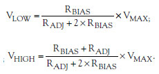
To compute the appropriate high- and low-side bias-resistor values, the following equations solve this circuit as a simple voltage divider:
Substituting and solving for RBIAS and given that the maximum voltage reports a value of 255, the maximum low voltage reports a value of 78, the maximum high voltage value reported is 178, and RADJ has a value of 5 kΩ yield the following equation:
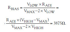
The computed value of RBIAS is 3875Ω. Using a standard value of 3.3 kΩ, the potentiometer’s input ranges from 73 to 182. This range yields a larger dynamic range than you need but allows for a guard range between the potentiometer’s values and the pushbuttons’ values. Because the position of RADJ affects the overall resistance the circuit sees when you press either switch, the microcontroller must interpret a range of values for each switch. To determine the switch resistance, RSW, for either S1 or S2, you use a parallel-resistor network at both extremes of the potentiometer’s position.
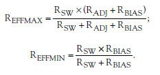
When you press S1 and RADJ is at the maximum position, the effective resistance of the bottom leg of the divider is RSW in parallel with the series combination of RADJ and RBIAS. At the minimum position, the effective resistance is RSW in parallel with RBIAS:
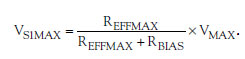
You determine the value when you press S1 by evaluating the voltage divider that RBIAS and RRFFMAX form:
Observe that when RADJ is at its maximum value and you press S1, it must produce a value less than the smallest value RADJ produces by itself to uniquely determine that you have pressed the switch. So the maximum effective resistance, REFFMAX, must produce a value less than the maximum low voltage, as the following equation shows:
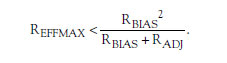
Substituting and solving this equation for the switch resistance yields:
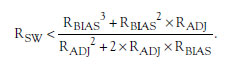
Using the spreadsheet to compute the switch resistance yields 1558Ω, and you can choose a nominal 1.5-kΩ resistor. This selection causes S1 to produce a range of 28 to 71 when you press it, depending on the potentiometer’s position. Likewise, choosing the same value for S2 produces a range of 184 to 227. These ranges are bands of values that you can use to determine which switch you pressed regardless of the potentiometer’s position. Although selecting symmetrical resistor values is not necessary, it minimizes the number of calculations you need to perform and simplifies the design. Furthermore, selecting smaller series switch resistors opens the guard range between them and the potentiometer, which may be desirable if the resulting values are too close together. The microcontroller uses a small subroutine, Listing 1, to determine both switch positions and the potentiometer’s setting.
The limitation of this technique is that you cannot press more than one pushbutton at any time. In addition, the microcontroller can read the potentiometer’s position only when you are not pressing any other pushbuttons. This example shows how to use two pushbuttons, but the number of pushbuttons can vary. Input ranges are available for as many as 10 pushbuttons and one potentiometer, all of which share the same input pin. Although the computed ranges do not overlap and are unique, it is doubtful that your ADC hardware can reliably distinguish these bands under all circumstances. Choosing smaller resistor values keeps these bands farther apart, creating a larger guard range.
Using this technique with four pushbuttons and one potentiometer is well within reason. Experimenting with the spreadsheet helps make quick work of determining just the right series-resistor values for each switch and its output range.