Targeted for the smart home, this design leverages two PIC MCUs that use a wireless RF transmitter/receiver to control up to six relays and monitor two analog signals.
In this design idea, you will learn how to interface two PIC microcontrollers using a wireless 433-MHz RF transmitter/receiver pair to control up to six relays and monitor two analog signals. The design will find multiple applications intended for smart-home systems. The RF modules (PT2262/PT2272) used in this setup are available from Digi-Key (P/N: 1597-1223-ND).
 |
|
| Figure 1. | Shown is the circuit for the relay transmitter based on the microcontroller PIC16F1619. |
Figure 1 shows the transmitter based on the microcontroller PIC16F1619. Pushbuttons PB1 thru PB4 are enabled to control four relays in the receiver module in Figure 2.
 |
|
| Figure 2. | Here’s the receiver that controls six relays based on the PIC16F1619 microcontroller. |
Pushbuttons PB5 and PB6 are used to set the voltage thresholds for the temperature sensor applied on input RC6, and the potentiometer connected on RC7 in the microcontroller. These two readings control Relays 5 and 6, respectively, in the receiver module.
This feature can be used to operate as a thermostat in A/C systems.
PB5 and PB6 are configured to set up temperature and voltage, respectively. Temperature can be set in intervals of 1 °C. The second signal that can be measured is voltage. It can be set in intervals of 10 mV, setting the maximum voltage to 4.99 V.
When setting the values of temperature and voltage, an interval is created, in which their state doesn’t change. This is called hysteresis. When the temperature increases ±1 °C, the voltage changes with a resolution of 10 mV. If the voltage or temperature is within two intervals, it will remain in the last active state, either On or Off. This is used to avoid damaging the connected relays.
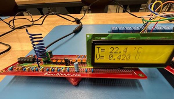
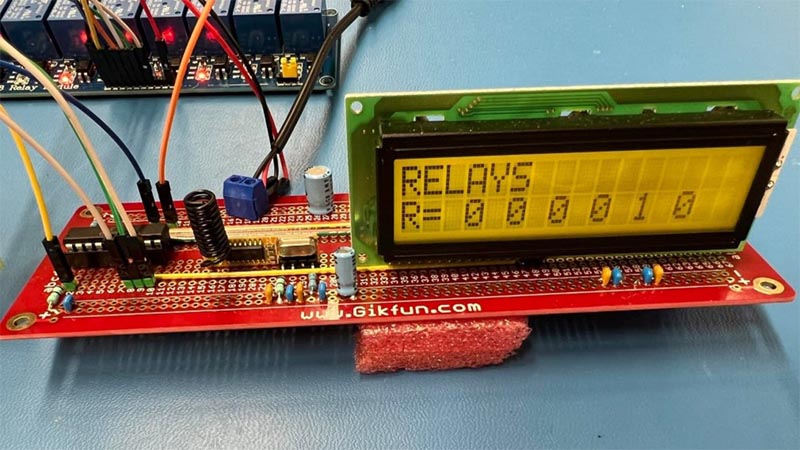
Listings 1 and 2, available in the Downloads section, show the code for the transmitter and receiver modules, respectively. The transmitter module displays the actual temperature detected by the LM34 sensor, and the voltage coming from the trim potentiometer. The receiver module displays the status of each relay.
This circuit uses the EUSART (Enhanced Universal Synchronous Asynchronous Receiver Transmitter) modules embedded in two PIC microcontrollers 16F1619 and 16F1614. The communication is full-duplex between both devices (Rx and Tx).
To establish communication, it’s necessary to have a starting bit for a period of time to alert the receptor that a data package is about to be transmitted. This allows the receiver clock to start synchronization with a 0 bit. Then each bit is sent individually, starting with the LSB bit through the MSB bit. Each bit has the same period. Once all bits are transmitted, it has to wait for the high-logic Stop bit to indicate end of transmission. [1]
 |
|
| Figure 3. | This is the assembled PCB transmitter. |
Figures 3 and 4 show the actual assembled circuits in two printed circuit boards.
 |
|
| Figure 4. | The PCB for the receiver unit displays relay status. |