Piezoelectric buzzers find wide use as audible-signal generators because of their low power consumption and clear, penetrating sound. An external driver or a self-driven circuit that oscillates at the resonant frequency of the piezoelectric element can drive these buzzers. A piezoelectric element produces the maximum sound output at its resonant frequency. However, the resonant frequency of a piezoelectric element can have a tolerance as great as ±15%. An external driver tuned to the nominal resonant frequency is therefore likely to miss the actual resonance point. This Design Idea externally drives a piezoelectric element and automatically finds its actual resonant frequency.
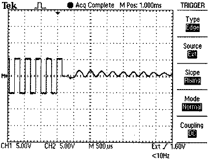
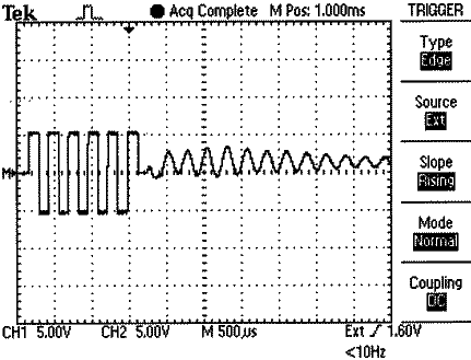
The basis for operation is the following principle: When you apply an alternating voltage to the terminals of a piezoelectric element, the element will begin to vibrate. If you remove the excitation, vibrations will continue in a damped manner before they cease altogether. These residual vibrations will cause damped oscillations at the terminals of the piezoelectric element. If the excitation is close to the resonant frequency, the vibrations will be stronger and the residual oscillations will last longer (Figure 1). You can determine the actual resonant frequency by trying all the frequencies around the nominal resonant frequency and comparing the duration of residual oscillations.
 |
|
| Figure 1. | At a frequency of 4 kHz, which is closer to the resonant frequency, residual oscillations last longer (a) than the resonant frequency with 3.2 kHz (b). |
In this design, a Microchip PIC18F452 microcontroller drives a piezoelectric element through its I/O pins, RB4 and RB3 (Figure 2). Initially setting RB3 to zero and RB4 to one and toggling them after each half-period generates an alternating piezoelectric voltage (VP) with a 0 V-dc bias. After applying 10 cycles, RB3 is kept low, and RB4 is made an input to count the low-to-high and high-to-low transitions of VP. Enabling the “interrupt-on-port-change” feature of Port B for 10 msec and incrementing a counter in the interrupt-service routine counts the transition of the piezoelectric voltage. Listing 1 demonstrates this feature. The program repeats these steps for all frequencies of interest and identifies the frequency corresponding to the maximum number of transitions at the resonant frequency. You can easily expand the idea for the case of multiple resonant frequencies.
 |
|
| Figure 2. | A PIC18F452 microcontroller first drives the piezoelectric buzzer at a programmed frequency and then configures one of its pins as an input to count the residual oscillations. |
