You can build a self-oscillating H bridge by replacing the pullup collector resistors of a classical BJT (bipolar-junction-transistor) astable multivibrator with PNP BJTs (Figure 1). Because this circuit oscillates at supply voltages as low as 0.6 V, you can use it in general low-voltage, low-power push-pull applications. You can, for example, drive a diode-capacitor charge pump to generate negative supply voltage in battery-powered systems. This Design Idea shows how to use it to light a white LED from one cell without an inductor.
 |
|
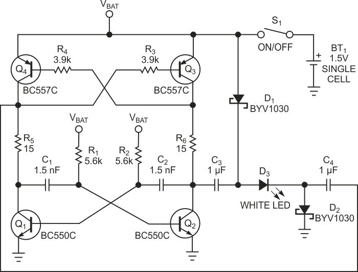
| РFigure 1. | Resistors R1 and R2 and capacitors C1 and C2 set the oscillation frequency. |
Transistors Q1, Q2, Q3, and Q4 form the H bridge, which acts as a simple charge-pump converter and requires only two small, inexpensive ceramic capacitors, C3 and C4, to perform its function. When Q2 and Q4 are on, capacitors C3 and C4 charge to the battery voltage through forward-biased Schottky diodes D1 and D2. When Q1 and Q3 are on, they discharge the capacitors through resistors R5 and R6 and the LED. Because this process repeats at a high rate of speed, the LED appears always on.
The circuit oscillates with a frequency based on time constants R1C1 and R2C2. During discharge, the voltage that develops across resistors R5 and R6 and the LED remains approximately constant because of the high switching frequency. The measured value, for a nominal 1.5 V battery voltage, is 3.8 V – enough to drive a white LED with a forward voltage of 3 to 3.5 V. Resistors R5 and R6 set the LED's peak current and limit the possible current spikes that a push-pull output stage can produce.
Choosing the astable oscillator's frequency involves a trade-off between the time necessary to charge capacitors C3 and C4 and the need to reduce their discharge. For a given capacitance value of C3 and C4, you must experiment to find the optimum frequency. With the component values in Figure 1, the frequency and the duty cycle are about 66 kHz and 50%, respectively, and the LED's drive current is a square-wave signal with 20-mA peak value and 10-mA average value. The LED dims gradually as the battery voltage decreases, and the LED is off when the battery voltage falls below 0.9 V. For high efficiency, use small-signal transistors with high dc current gain and low collector-to-emitter saturation voltage. Note that the circuit can drive any type of LED; in this case, you should increase current-limiting resistors R6 and R5 to achieve the LED-drive current your application requires.