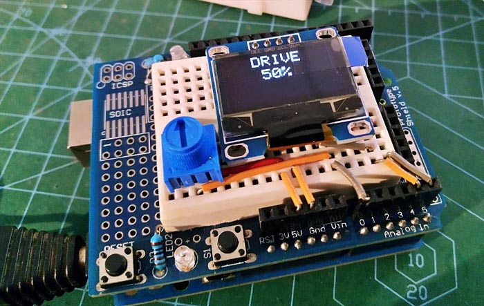
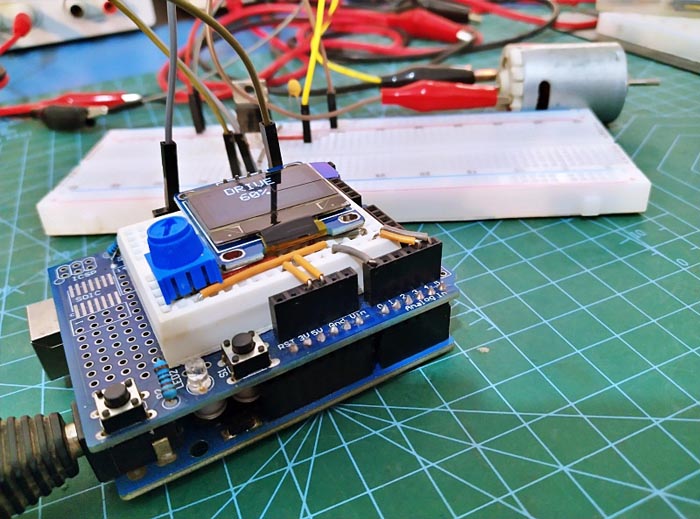
This handheld electric PCB drill speed controller is cheap, easy to build, and only uses a few components. Basically, it is an Arduino Uno based PWM controller that operates at a relatively high frequency (Figure 1). It features almost 0-100% DC motor speed regulation while retaining the pulse width modulation frequency pretty stable. It also has an OLED display to show the PWM duty cycle!
 |
|
| Figure 1. | Electric hand drill controller with OLED display. |
As you guessed, the PWM control here works by switching the power delivered to the DC motor on and off rapidly. The drive voltage is converted to a square wave signal, alternating between fully on and fully off, giving the motor a series of power pulses. By adjusting the duty cycle of the PWM signal (by modulating the width of the pulse), the average power can be varied, thus the motor speed. Note that if the switching frequency is high enough, the motor runs at a steady speed.
Now let's take a look at the Arduino sketch, which can be downloaded from the link in the Downloads section.
This code delivers a single channel pulse width modulated motor drive signal thru Arduino Uno’s PWM pin D5. The duty cycle of the drive signal can be varied through the user interface which is nothing but a linear potentiometer connected to the analog input pin A0 of the Arduino Uno microcontroller.
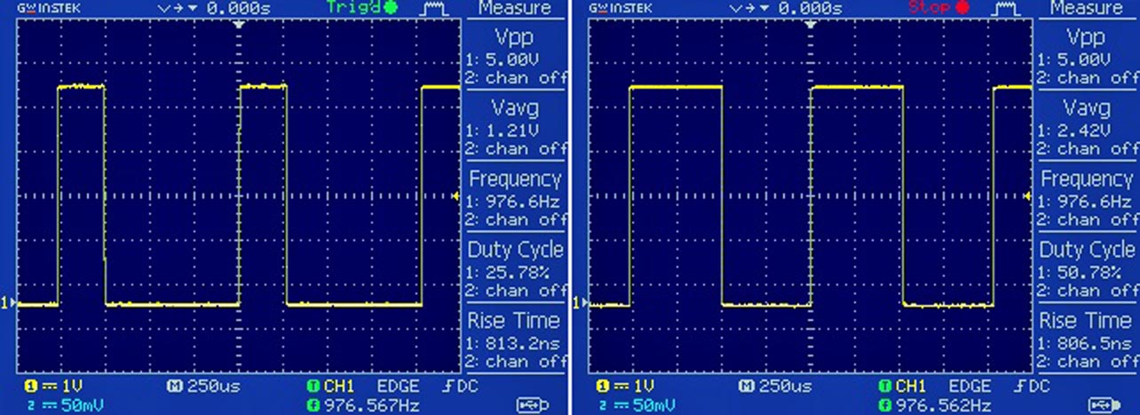
The PWM drive frequency is loosely 976 Hz (see oscillograms in Figure 2). It is worth noting that the exact PWM frequency for D5 is 976.56 Hz (default).
 |
|
| Figure 2. | Waveforms of PWM signals. |
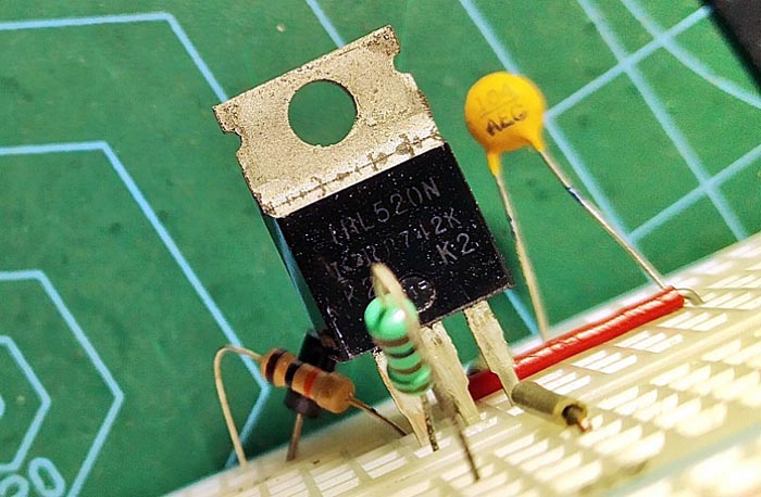
For the motor driver transistor I used the IRL520N MOSFET. It is easy to find, not expensive, and has only 0.27 Ω RDS(on) at 5 V VGS so you lose very little from the power source at full speed. Most N-channel “logic level” Power MOSFETs will do, look for a low RDS(on) and adequate current-handling ability. A heatsink is not necessary at moderate loads like our handheld electric PCB drill.
You can see that in the setup in Fgure 3, there is a regular rectifier diode antiparallel to the inductive load (the dc motor) we are powering. Note that any time you are powering a motor, you need this as when you stop powering the motor, a harmful reverse voltage spikes back, but the diode routes it back to the motor and not the delicate motor driver circuitry.
 |
|
| Figure 3. | IRL520N transistor and anti-parallel diode. |
At first, I tried my prototype with a RS-555 12 VDC motor (Figure 4), which worked like a charm!.
 |
|
| Figure 4. | Prototype testing. |
For testing, a 6F22 9 V battery was used for the small current Arduino setup, and a separate 12 VDC/2 A power supply for the beefy motor (both had a common ground rail).
However it is observed that at the minimum speed setting my test motor ran fine but would not start from a standstill. Also the full-power PWM drive will run the motor at a bit lower speed than an equivalent steady dc voltage.
Also keep in mind that MOSFETs often generate RFI when switching. So if you get any evidence of RFI, it can be damped with a small ferrite bead threaded onto the gate resistor lead closest the gate of the MOSFET.
Moreover, when it comes to the motor switching theory, AFAIK the best switching conditions are when the switch frequency is much higher than the dynamics of the motor. Due to different references the frequency must be at least x5 higher than the rotation speed of the motor (such a higher frequency also avoids noise from the motor in the audio range).
I do not think much about these failings but will make some modifications in the next version.
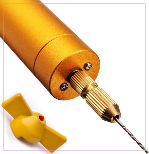
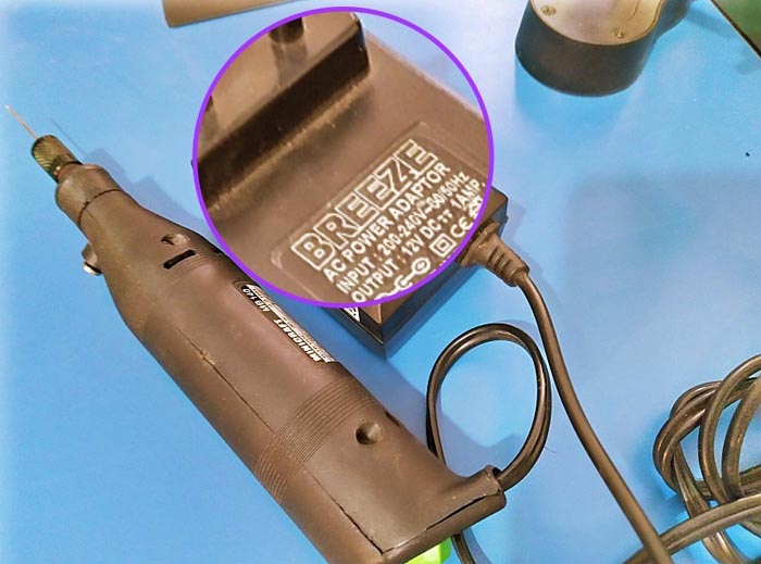
Later I made a second attempt with my old (locally-purchased) handheld electric PCB drill powered by its own 12 VDC/1 A SMPS adapter (see Figure 5). It still works, and is currently in use as I write this post.
 |
|
| Figure 5. | An old handheld electric drill for circuit boards. |
Finally, Figure 6 is the self-explanatory schematic for you to follow.
 |
|
| Figure 6. | Schematic diagram of a handheld electric drill controller. |
So, now you have a budget replacement for the old-hat 555 timer based PWM controller to regulate speed of a dc motor. A small number of parts, display panel to show the drive level, and room of creative betterments by tweaking the firmware makes it a much better alternative. Of course, governing the speed of an electric drill is not the only application for a power PWM driver like this, so use it for whatever you fancy. Have Fun!