This project is an ultrasonic range finder built using the RP2040 Zero board and a 3.2-inch TFT display. It utilizes the RCWL-1655 sensor, which operates similarly to the popular HC-SR04, to measure distances ranging from 20 cm to 300 cm. The device features a relay and a buzzer, each with its distance threshold. All settings, including the thresholds and buzzer status, can be adjusted using a simple graphical user interface (GUI). The GUI (Ref. 1) is controlled using just two push buttons – one for moving between options and one for selecting them, making it easy to use.
Circuit analysis
Figure 1 shows the schematic diagram of the range finder. The heart of the circuit is the RP2040-Zero board, which controls the LCD, buzzer, ultrasonic module, and the relay. Let’s first explain each hardware part.
 |
|
| Figure 1. | Schematic diagram of the ultrasonic range finder. |
RP2040 Zero
The Waveshare RP2040 Zero is a compact development board built around the Raspberry Pi RP2040 microcontroller. Designed to balance performance and size, it is well-suited for embedded projects with compact size (Figure 2).
 |
|
| Figure 2. | Waveshare RP2040 Zero board pinout. |
Here are some key features and specifications of the Waveshare RP2040 Zero.
Key features
- Microcontroller: Dual-core ARM Cortex-M0+ processor with a clock speed of up to 133 MHz.
- On-chip memory: 264 KB SRAM.
- Flash storage: 2 MB onboard QSPI flash for program and data storage.
- GPIO pins: 20 GPIO pins, supporting I2C, SPI, UART, PWM, and ADC functionality.
- Compact design: Tiny form factor similar to the Raspberry Pi Zero, ideal for space-constrained applications.
- Pin compatibility: Standard pin headers for easy integration with breadboards or other hardware.
- Programmability: Compatible with C/C++ and MicroPython programming environments.
- Power supply: Supports a 5 V input through USB or external sources, with an onboard 3.3 V regulator.
The Waveshare RP2040 Zero features make it an excellent choice for hobbyists and professionals.
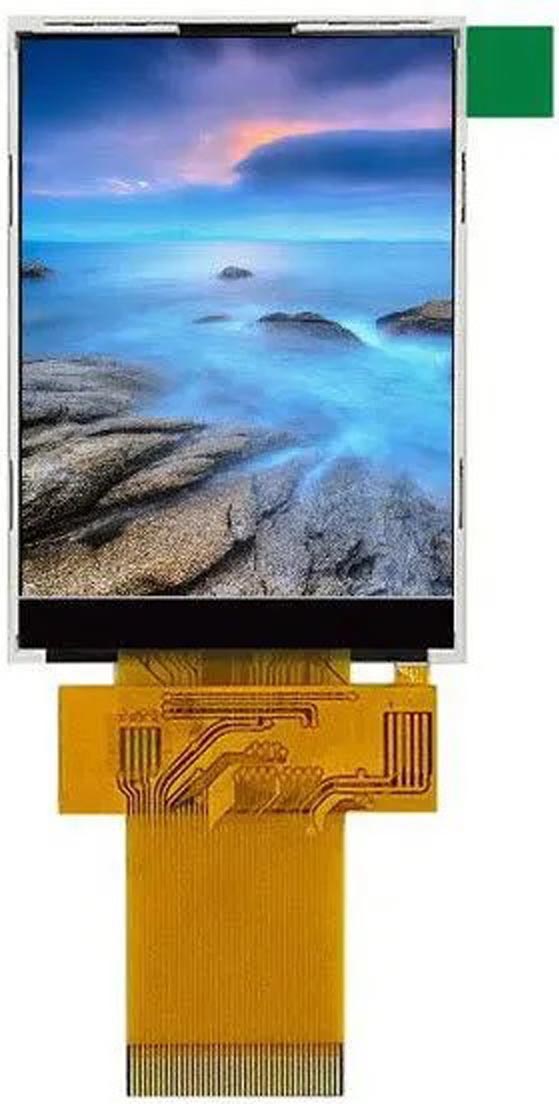
ILI9341 320×240 TFT display
The ILI9341 320 × 240 TFT display is a vibrant and versatile graphical display module commonly used in embedded projects for resolution, full-color capability, and ease of interfacing. It is based on the ILI9341 driver IC, which offers robust performance and compatibility with popular microcontrollers. Also, most coding IDEs include libraries to support this chip, such as the TFT_eSPI library for Arduino. The bare 40-pin flat LCD cable supports SPI and parallel data transfer, which should be selected via three pull-up/pull-down resistors. I selected the SPI interface. Figure 3 shows the pinout.
 |
|||||||||||||||||||||||||||||||||||||||||||||||||||||||||||||||||||||||||||||||||||||
|
|||||||||||||||||||||||||||||||||||||||||||||||||||||||||||||||||||||||||||||||||||||
| Figure 3. | ILI9341 40-pin TFT LCD flat cable pinout. | ||||||||||||||||||||||||||||||||||||||||||||||||||||||||||||||||||||||||||||||||||||
Key features
- Resolution: 320 × 240 pixels, offering a crisp and detailed graphical interface.
- Display size: 2.4-inch, 2.8-inch, or 3.2-inch variants are commonly available.
- Color depth: 65K or 262K colors, supporting rich and vivid visuals.
- Backlight: LED backlight with adjustable brightness.
- Touch support: Touch-enabled (resistive or capacitive) and non-touch variants are available.
- Interface: SPI (4-wire or 3-wire) and sometimes parallel interfaces for high-speed communication.
- Power supply: Operates at 3.3 V logic levels but often includes a regulator for 5 V compatibility.
- Driver IC: ILI9341, known for its efficient rendering of complex graphics and smooth operation.
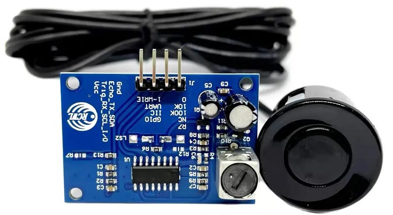
RCWL-1655
The RCWL-1655 is a waterproof ultrasonic distance measuring module designed for accurate and reliable distance detection in various environments. It is particularly suitable for applications that require resistance to moisture and dust, such as outdoor or industrial settings (Figure 4). The circuit is compatible with various 5 V ultrasonic modules that use ECHO and TRIG pins, so you are not limited to this specific model.
 |
|
| Figure 4. | The RCWL-1655 ultrasonic module. |
USB is the USB4135 Type-C connector. R16 and R17 are pull-down resistors, indicating this Type-C port is configured as a “load”. However, since the circuit’s maximum current consumption is less than 200 mA, these resistors are not strictly required.
USB power (Net: +5V-R) is connected to R2, C4, C6, and C7 RC filter network for noise reduction and stabilization. REG is the AMS1117-3.3 +3.3 V LDO regulator providing a stable +3.3 V rail. D3 is an 0805 SMD LED indicating supply connection and its true voltage level. C10 and C11 are output capacitors to stabilize the regulator and reduce the noise.
T1 is the BSS138 N-channel SOT23 MOSFET to switch the relay. D5 protects the MOSFET against relay’s bobbin reverse currents, and C12 dampens any inrush or spike. R10 is a pull-down gate resistor to prevent any unwanted switching. D4 is an 0805 red LED to present the ON/OFF status of the relay.
T2 is another BSS138 MOSFET to switch the buzzer. USRF is a 4-pin male XH connector for the ultrasonic module wires. C8 and C9 are decoupling capacitors for the supply rail.
R11, R14, T13, and R12, T4, R15 are to convert the ultrasonic ECHO and TRIG pins from 5 V to 3.3 V logic. This is the most cost-effective available solution, which functions properly.
RP is the RP2040-Zero board. C3 and C5 are decoupling capacitors. D1 is the SS14 SMA Schottky diode to separate the 5 V supply of the RP2040 debugging port from the board’s supply. This separation enables the user to simultaneously power the circuit and debug the code using a PC. D2 is a blinking LED that indicates the board functions properly.
LCD is a 40-pin 0.5 mm-pitch FPC connector for connecting the LCD flat cable. C1 and C2 are decoupling capacitors. R6, R7, and R8 are configuration resistors used to set the LCD to SPI and disable the parallel communication.
PCB layout
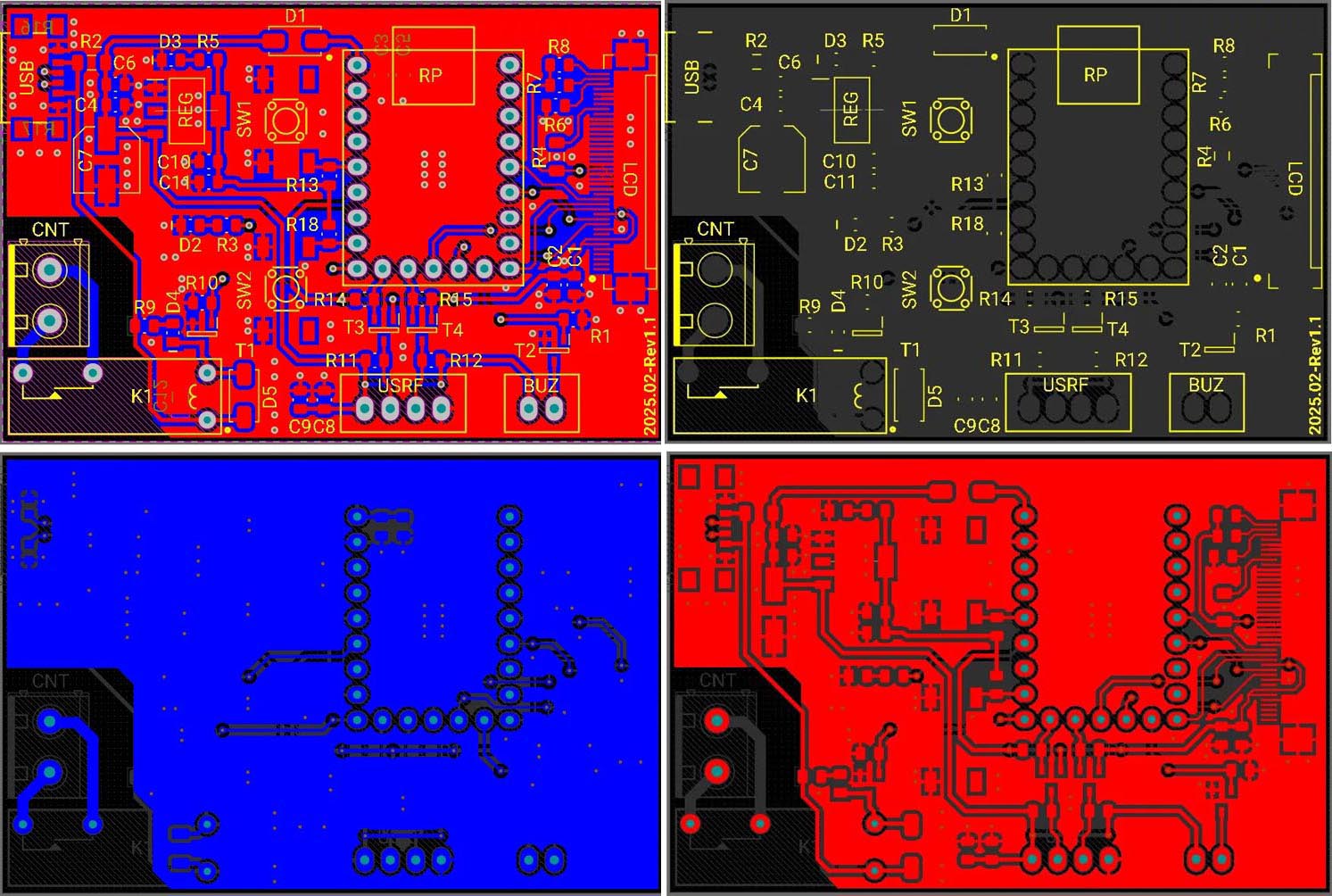
Figure 5 shows the PCB layout of the rangefinder. The Gerber files and firmware for the RP2040 Zero are available in the Downloads section. It’s a two-layer PCB. If we divide the PCB into functional parts, each part is located within a region. This is the most important rule in PCB design.
 |
|
| Figure 5. | PCB layout of the ultrasonic range finder circuit. |
No copper planes or tracks are placed near the relay’s switch and its terminal, as the user might connect high voltage DC or even AC loads to the terminal. Where necessary, ground copper planes and stitching vias are used. Figure 6 shows the PCB assembly drawing.
 |
|
| Figure 6. | PCB assembly drawing. |
Assembly and test
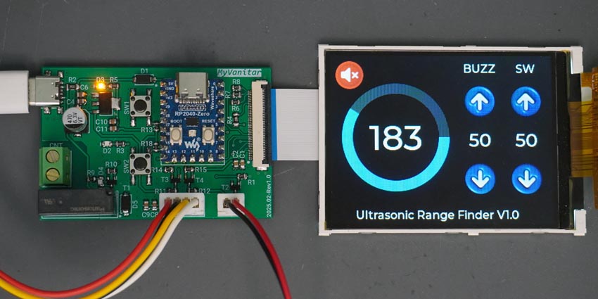
Figure 7 shows the assembled board. It’s quite easy to use the board: interact with the push buttons, navigate between widgets, set your desired value, and even turn the buzzer ON or OFF.
 |
|
| Figure 7. | Operational board showing the GUI and connected hardware. |
References
Materials on the topic
- Datasheet Waveshare RP2040-ZERO
- Datasheet AMS AMS1117
- Datasheet ON Semiconductor BSS138
- Datasheet Vishay SS14
- Datasheet Panasonic ALDP105
- Datasheet GCT USB4135