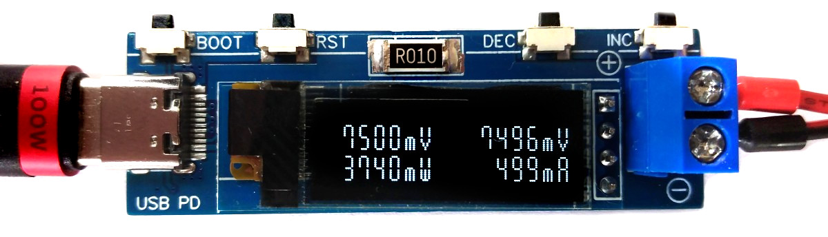
The USB PD adapter shown in Figure 1 is is a compact variable power supply capable of utilizing nearly any USB Type-C PD power supply with PPS-feature as an input to power your projects with various selectable voltages and high currents. Key parameters such as voltage, current, power, and energy are conveniently displayed on the OLED screen. This adapter is built around the cost-effective (30 cents at the time of writing) and user-friendly CH32X035 32-bit RISC-V microcontroller, which features hardware USB PD support, along with the INA219 voltage and current sensor IC.
 |
|
| Figure 1. | USB PD adapter. |
Hardware
Schematic
 |
|
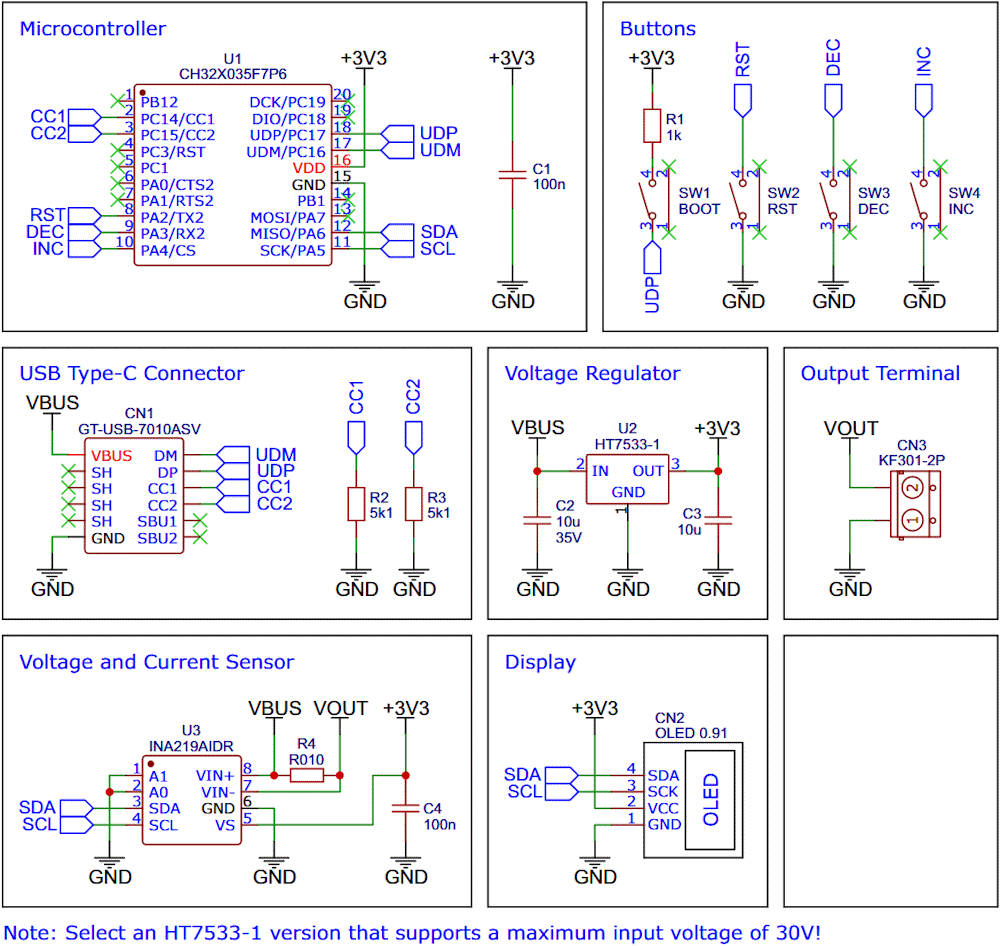
| Figure 2. | Schematic diagram of the USB PD adapter. |
Figure 2 shows the schematic diagram of the USB PD adapter. Table 1 shows the bill of materials.
| Table 1. | Bill of materials | ||||||||||||||||||||||||||||||||||||||||||
|
|||||||||||||||||||||||||||||||||||||||||||
CH32X035 F7P6 32-bit RISC-V USB microcontroller
CH32X035F7P6 is a low-cost microcontroller that utilizes the QingKe 32-bit RISC-V4C core, supporting the RV32IMAC instruction set along with self-extending instructions. This microcontroller comes with a built-in USB PHY, supporting USB2.0 full-speed device functions and a USB PD PHY with source and sink capabilities. It features a programmable protocol I/O controller (PIOC), an operational amplifier (OPA) with programmable gain (PGA), an analog comparator (CMP), a 12-bit analog-to-digital converter (ADC), an 11-channel touch-key controller, 3 groups of USART, I2C, SPI, multiple timers, and various other peripheral resources. The device can operate at clock frequencies of up to 48 MHz and is compatible with a supply voltage range of 2.0 V to 5.5 V. The CH32X035F7P6 includes 48 KB of flash, 20 KB of SRAM, and an embedded USB bootloader.
The CH32X035 microcontroller manages several tasks, including power negotiation with the USB PD power supply, INA219 management, user interface control, and computation and presentation of measured values. The user interface is comprised of three buttons and an SSD1306 I2C OLED display with a resolution of 128×32 pixels.
INA219 current/power monitor
The INA219 is a current shunt and power monitor with an I2C-compatible interface. The device monitors both the shunt voltage drop and bus supply voltage, with programmable conversion times and filtering. A programmable calibration value, combined with an internal multiplier, enables direct readouts of current in amperes.
The selected shunt resistance of 10 mΩ enables both a very small influence on the circuit and a measurement with a resolution of 1 mA. For accurate measurement, a shunt resistor with a low tolerance (1% or better) should be selected. The INA219 is used here to measure the output voltage and output current. It communicates with the MCU via I2C.
HT7533-1 voltage regulator
The HT75xx-1 series comprises three-terminal high current low voltage regulators crafted using CMOS technology. They are capable of delivering an output current of 100 mA and can handle input voltages as high as 30 V. The utilization of CMOS technology guarantees minimal voltage drop and low quiescent current.
The HT7533-1 provides a stable 3.3 V supply to all components of the circuit. Ensure that you select a version with a maximum input voltage rating of 30 V.
SSD1306 OLED display module
A low-cost SSD1306 4-pin I2C 128×32 pixels 0.91-inch OLED module is used as the display device. Make sure to acquire one with the correct pinout!
Building instructions
- Take the Gerber files (download them from the Downloads section) and upload them to a PCB manufacturer of your choice. They will use these files to create the circuit board for your device and send it to you.
- Once you have the PCB, you can start soldering the components onto it. Remove the plastic part from the pin header of the OLED, trim the pins, and solder the OLED module flush onto the PCB.
- Upload the firmware by following the instructions in the next section (see below).
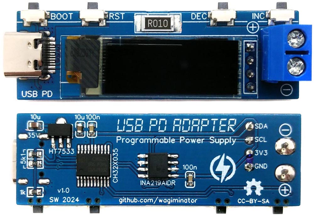
Figure 3 shows the assembled PCB board.
 |
|
| Figure 3. | Assembled PCB board of the USB PD adapter. |
Software
USB bootloader
Installing drivers for the bootloader
On Linux you do not need to install a driver. However, by default Linux will not expose enough permission to upload your code with the USB bootloader. In order to fix this, open a terminal and run the following commands:
echo 'SUBSYSTEM=="usb", ATTR{idVendor}=="4348", ATTR{idProduct}=="55e0", MODE="666"' | sudo tee /etc/udev/rules.d/99-ch55x.rules
echo 'SUBSYSTEM=="usb", ATTR{idVendor}=="1a86", ATTR{idProduct}=="55e0", MODE="666"' | sudo tee -a /etc/udev/rules.d/99-ch55x.rules
sudo udevadm
For Windows you can use the Zadig [1] tool to install the correct driver. Here, click "Options" -> "List All Devices" and select the USB module. Then install the libusb-win32 driver. To do this, the board must be connected and the microcontroller must be in bootloader mode.
Entering bootloader mode
The bootloader must be started manually for new uploads. To do this, the board must first be disconnected from the USB port. Now press the BOOT button and keep it pressed while reconnecting the board to the USB port of your PC. The chip now starts in bootloader mode, the BOOT button can be released and new firmware can be uploaded via USB within the next couple of seconds.
Compiling and uploading firmware using the makefile
Linux
Install the toolchain (GCC compiler, Python3, and chprog):
Install the toolchain (GCC compiler, Python3, and chprog):
sudo apt install build-essential libnewlib-dev gcc-riscv64-unknown-elf
sudo apt install python3 python3-pip
pip install chprog
Open a terminal and navigate to the folder with the makefile. Press the BOOT button and keep it pressed while connecting the board to the USB port of your PC. Run the following command to compile and upload:
make flash
Other operating systems
Follow the instructions on CNLohr's ch32v003fun page [2] to set up the toolchain on your respective operating system (for Windows, use WSL). Also, install Python3 [3] and chprog [4]. Compile and upload with "make flash". Note that I only have Debian-based Linux and have not tested it on other operating systems.
Compiling and uploading firmware using PlatformIO
- Install PlatformIO [5] and platform-ch32v [6]. Follow these instructions [7] to do so. Linux/Mac users may also need to install pyenv [8].
- Click on "Open Project" and select the firmware folder with the platformio.ini file.
- Press the BOOT button and keep it pressed while connecting the board to the USB port of your PC. Then click "Upload".
Uploading pre-compiled firmware binary
WCH offers the free but closed-source software WCHISPTool [9] to upload firmware with Windows via the USB bootloader. Press the BOOT button and keep it pressed while connecting the board to the USB port of your PC. Release the BOOT button, open the pd_adapter.hex file in the bin folder with WCHISPTool and upload it to the microcontroller.
If Python3 is installed, you can also use the platform-independent open-source command-line tool chprog for uploading:
chprog bin/pd_adapter.bin
Operating instructions
- Connect the USB PD Adapter to a USB Type-C PD power supply using a USB-C cable.
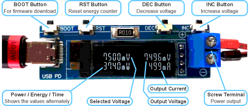
- Use the INC/DEC buttons to select the desired output voltage in steps of 20 mV (See Figure 4)..
- Connect the device to the power consumer via the output screw terminal.
- Use the RST button to clear the energy counter.
 |
|
| Figure 4. | USB PD adapter user interface. |
The program source code and the compiled HEX file can be downloaded from the link in the Downloads section.
References
- Zadig
- Installation
- Install Python
- USB Programming Tool for WCH Microcontrollers
- PlatformIO
- Platform-ch32v
- Install PlatformIO
- Managing Multiple Python Versions With pyenv
- WCHISPTool_Setup.exe
Materials on the topic
- Datasheet WCH CH32X035
- Datasheet Texas Instruments INA219
- Datasheet Holtek HT75xx-1
- Datasheet Solomon Systech SSD1306