Josef Valasek
EDN
If you develop an application on a small microcontroller, your diagnostic tools for debugging of the program code might be very limited. This Design Idea introduces a simple debugging routine for plotting the binary value of one byte on a scope display. It uses one output pin of the microcontroller.
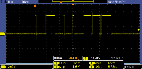
To display a byte value, load it into the accumulator and call the routine named Debug. The value is converted to serial and output on the port named Test (Figure 1). The most-significant bit is plotted first. Adding demarcation pulses between similar bits makes reading easy. If you need to display more than one byte, call Debug more than once.
 |
|
| Figure 1. | The scope says "01000111". |
An 8051 version is shown below. The routine uses no RAM; it uses R7 only. Execution time is 76 µs for a standard 12-clock 12 MHz 8051 core (including the call).
   ;****************************************************************
   ;*                                                              *
   ;*      Procedure:      Debugging Routine                       *
   ;*                                                              *
   ;*      Entry:          Data byte in Acc                        *
   ;*                                                              *
   ;*      Exit:           Serial of signals on port "Test"        *
   ;*                                                              *
   ;*      Affected:       Acc, r7                                 *
   ;*                                                              *
   ;*      Assembler:      KEIL, A51 MACRO ASSEMBLER               *
   ;*                                                              *
   ;****************************************************************
   Test    bit     P1.5            ; Diagnostic output port
           public  Debug
   SGC_DEBUG       SEGMENT CODE
           RSEG    SGC_DEBUG
   Debug:  push    psw             ; Save PSW
           mov     r7,#9           ; Number of cycles
           clr     EA              ; Disable all interrupts
           clr     c               ; Clear carry bit
   Loop:   rlc     a               ; Shift data bit to C
           jnc     Zero
   One:    clr     Test            ; "1" bit slice beginning
           setb    Test
           djnz    r7,Loop
   Zero:   setb    Test            ; "0" bit slice beginning
           clr     Test
           djnz    r7,Loop         ; Repeat for 9 bits
           setb    EA              ; Enable all interrupts
           pop     psw             ; Recover PSW
           ret
           END
A PIC versin is shown below. The routine uses 2 bytes of RAM & 2 registers.
   ;****************************************************************
   ;*                                *
   ;*      Procedure:      Debugging Routine                       *
   ;*                                                              *
   ;*      Entry:          Data byte in W                          *
   ;*                                                              *
   ;*      Exit:           Serial of signals on port "Test"        *
   ;*                                                              *
   ;*      Affected:       W, C, TempCtr, TempData                 *
   ;*                                                              *
   ;*      Assembler:      Microchip, MPASM                        *
   ;*                                *
   ;****************************************************************
           list    p=16F505,r=dec,c=93,n=63,st=OFF
           #include "p16F505.inc"

   #define Test            PORTB,1 ; Diagnostic Port
           global  Debug
   TempCtr         equ     H'0E'   ; Temporary Counter
   TempData        equ     H'0F'   ; Temporary Data
   DEBUG   CODE
   Debug   movwf   TempData        ; Save data byte
           movlw   9               ; Number of cycles
           movwf   TempCtr
           bcf     STATUS,C        ; Clear Carry bit
   Loop    rlf     TempData,F      ; Shift data bit to C
           btfss   STATUS,C
           goto    Zero
           nop
   One     bcf     Test            ; "1" bit slice beginning
           bsf     Test
           decf    TempCtr,F
           goto    Loop
   Zero    bsf     Test            ; "0" bit slice beginning
           bcf     Test
           decfsz  TempCtr,F
           goto    Loop
           retlw   0
           END
Using one of the ISP pins for output is a good solution, because you usually can connect a scope probe directly to the pin of the ISP programming connector.
Reference:
- Peeters, Brad, PIC debugging routine reads out binary numbers, EDN, December 7, 2000, p.196