Rick Demeis
EDN
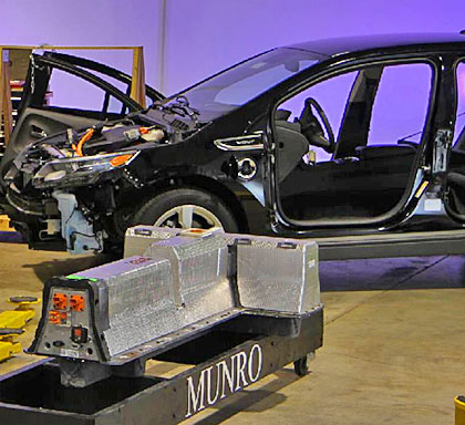
Engineers sometimes get assignments that are not only challenging learning experiences but also just plain fun. That scenario happened when John Scott- Thomas, UBM TechInsights’ product-marketing manager, and Al Steier, Munro & Associates’ senior associate and “design prophet,” recently took apart a Chevy Volt plug-in hybrid car to see what makes it tick, whir, and hum – and how its designers put together all of the technology in the car. Over the three days it took to creatively disassemble the Volt, they learned many things about the vehicle (see sidebar “Anatomy of an automotive teardown” and references 1 and 2).
Battery Pack
The 288-cell Volt lithium-ion battery pack comprises four modules in a T shape that fits below the rear seat and in the “tunnel” between the front seats. Bus bars connect the four modules, and a service-disconnect bar connects to the pack contacts (Figure 1). The pack physically divides into plastic-encased slices, or blades, each of which includes two cells. A cooling fin carrying five channels of coolant separates the two cells. Electrically, groups of three cells connect in parallel, and 96 of these groups are in series so that the 288 cells produce 360V with a capacity of 16 kWhr. To prolong battery life, the battery never fully charges or discharges, so it uses only the “middle” 9.4 kWhr of battery energy.
 |
|
| Figure 1. | The 375-lb (170-kg) lithium-ion battery pack is the heart of the Volt. The vehicle’s systems and software maintain the battery pack’s health for a long service life (courtesy Munro & Associates). |
LG Chem manufactures the battery, which uses lithium-manganese-spinel chemistry, but GM has licensed battery cobalt chemistry from the US Argonne National Lab, indicating that a switch to a nickel-manganese-cobalt battery could be in the offing. The batterycooling-fluid circuit is one of four in the Volt, each with its own controller and radiator module. The other three loops are for the internal combustion engine, the two electric motor/generator inverters, and the power-line plug-in charger’s power converter.
When the battery is operating at lower than the optimum operating temperature, the fluid heats the battery to operating conditions and then cools it to avoid overtemperature. Even if the car is not operating, the control electronics activate the coolant loop to avoid overheating the battery during hot weather or overcooling in cold weather. Thus, keeping the Volt on its external charger when the car is not in use avoids draining the battery under such conditions.
The battery-pack coolant loop connects using hose clamps, indicating that the car is a limited-production vehicle. Higher production volumes would allow use of brazed joints. The bolts clamping together the pack each have three inspectors’ paint marks, showing that the assembly is carefully inspected to ensure quality and function for this $8000 component that is at the heart of the Volt.
Control and Monitoring
The complex Volt battery pack, as the teardown revealed, has equally sophisticated control and monitoring, which are typical of the entire car. Scott-Thomas observes that 40% of the value of the vehicle is in its electronics, typified by the nearly 100 onboard microcontrollers. Nearly 10 million lines of code control this electronic suite – more code than it takes to control the Boeing 787 Dreamliner, at 8 million lines.
As for the battery pack itself, Scott-Thomas notes that long battery life is a key objective. Toward this end, the manufacturer regulates pack temperature to within 2°F and balances cell charge between cells so that each ages at the same rate. The control software also factors in differences in manufacturing and other variables in aging.
For example, the controllers monitor voltage on each cell during charging. To ensure the same maximum charge on each, if one cell reaches capacity early, a resistive shunt across the cell connects to prevent it from being overcharged while the other cells come up to full charge. “The level of control and software is hard to appreciate,” says Scott- Thomas. The car’s controllers monitor the battery pack’s voltage and temperature with 500 diagnostics 10 times every second, with control activity even when the car is at rest.
 |
|
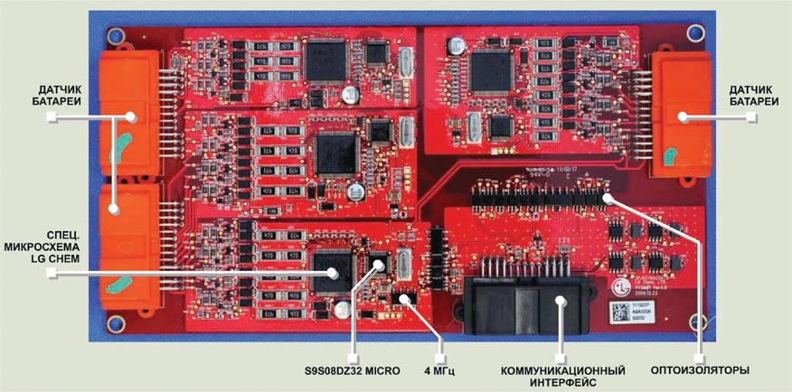
| Figure 2. | On the battery-interface/battery-monitor PCB, sensors on each cell monitor temperature and voltage. Their data routes in clusters, in which readouts for 10 cells are on one circuit that digitizes to a microcontroller. An optoelectric coupler feeds a common bus to the main controller in the inverter module (courtesy Munro & Associates). |
The battery-interface and monitoring module mounts atop the pack’s front. This unit has four orange monitoring PCBs, indicating high voltage – one for each pack section (Figure 2). Freescale, LG Chem, and STMicroelectronics chips populate these PCBs; the LG Chem and STMicro chips use bipolar CMOS DMOS (diffused-metal-oxidesemiconductor) technology. Midvoltage boards are blue, and low-voltage PCBs are green. Quality checks are in place throughout the manufacturing process; each cell connector bears multiple inspectors’ marks.
Getting the battery electronics correct is difficult; the system must measure within several millivolts at the top of each cell, while a cell can be offset from ground by hundreds of volts. This task requires attention to PCB layout, trace design, ground planes, and voltage isolation techniques. Scott-Thomas observes that the car’s design is a work in progress, with flexibility and modularity to easily introduce new cells, battery packs, electronics, and controls.
The teardown team discovered one unexpected battery-related module in the Volt. In addition to the standard onboard-diagnostics port under the driver’s side dashboard, the team found a sealed and potted module under the front passenger seat. This module stores battery- and hybrid-operation diagnostic codes and has a connection for an appropriate cable for a technician to access them.
Charging System
Besides using regenerative braking, the battery pack stores energy by charging from the power grid using the supplied 110V charger or an optional 220V charging station – for faster recharging – installed by a licensed electrician (Reference 3). Lear Corp manufactures the 110V home charger whose power electronics and software are sophisticated enough that charging does not occur if the user plugs it into an insufficiently grounded circuit. The charger’s relays and monitoring-electronics board communicate with the battery pack and onboard monitoring systems. As noted previously, the onboard system for changing ac power mains into dc power to charge the battery has its own cooling loop.
The charger plugs into a standardized receptacle behind a door on the left front fender. According to Scott- Thomas, dismantling this interface unit reveals GM’s attention to design detail. The manufacturer taped and foam-isolated the high-voltage components – that is, the capacitors and the common-mode choke – in this highvibration environment for robustness and protection, and windings are robust, stable, and mechanically redundant.
Steier found one puzzling feature with the charger configuration: Although the charger receptacle is on the left fender, the charging inverter it feeds is under the right headlight. Likewise, the gas-engine controller is on the left side, whereas the engine is on the right. Such an arrangement has greater wiring weight than if the manufacturer had reversed this configuration.
Brains of the Volt
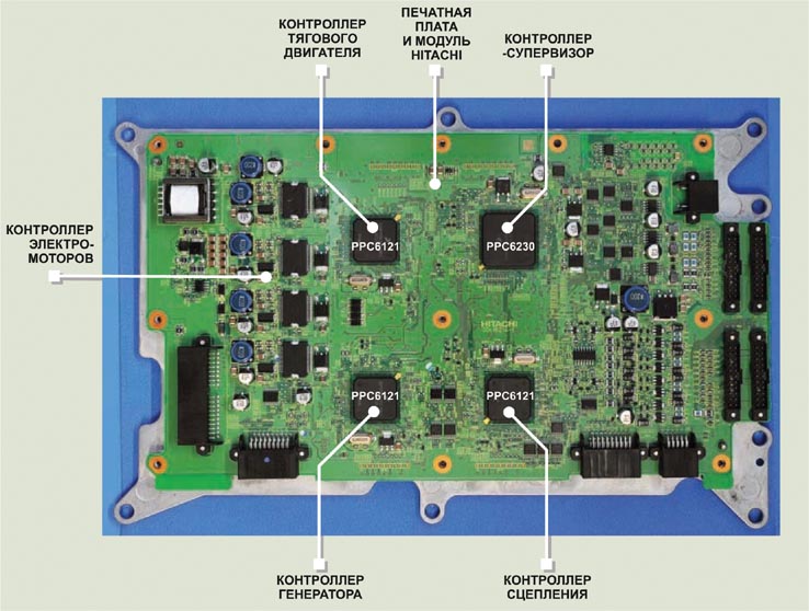
On the electric motor and generator housing, which looks like the transmission case of a gas-engine car, a liquid-cooled inverter module feeds battery power into the traction motor. The high-voltage orange cables leading to this module have disconnects with relays for safety; Steier notes that the module cover itself is also a safetycircuit disconnect. Inside is what Scott- Thomas says is the closest thing to a central brain in the car (Figure 3).
 |
|
| Figure 3. | The motor/generator inverter module contains the brains of the Volt power train, in which one supervisory microcontroller and three others define the operating state of the drive and the regenerative-braking system (courtesy Munro & Associates). |
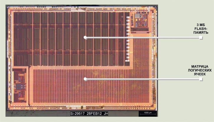
The Hitachi PCB includes four 32-bit Freescale Qorivva microcontrollers. Scott-Thomas first noticed the large amount of real estate available, noting that it allows future modifications, either by changing or adding circuits. One of the four controllers functions as the supervisor, using inputs, including vehicle and wheel speeds; acceleration, or throttle; braking; and battery state, to decide which state is the most efficient (Figure 4). Decisions to be made could include, for instance, choosing which combination of outputs from the traction motor and combustionengine- generator motor to use, when to activate regenerative braking, and to what extent to recover energy. The supervisory controller is the largest of the four microcontrollers, with 3 Mbytes of flash memory, taking half the area of the die. The controller also endeavors to run the electric motors at lower rotation rates for more efficiency. The other three Freescale microcontrollers control the traction motor; the combustion-enginedriven generator; and the clutched planetary gear set, which the IC engine can engage if necessary.
 |
|
| Figure 4. | The inverter’s supervisory controller is the center of the Volt’s hybrid architecture and determines current power-train state (courtesy Munro & Associates). |
Other Electronics
The rest of the Volt’s electronics, unless they connect with the hybrid-drive system, are fairly conventional state-ofthe- art automotives (Figure 5). An aircooled dc/dc converter, with PCBs from TDK and a Renesas microcontroller, takes the place of an alternator to provide 12V for running standard auto systems, such as doors, lights, navigation, and audio, and to charge the auxiliary 12V battery.
Taking apart the center stack uncovered a communications-module PCB by LG hosting a Freescale memory controller with Spansion flash. These infotainment boards are sparse, according to Scott-Thomas, who notes there is a lot of space but not that much required processing power; thus, the electronics combine several functions onto single chips. In addition, adequate space between the resistive-touch switches on the front of the panel helps prevent the driver from incorrectly selecting the wrong function.
 |
|
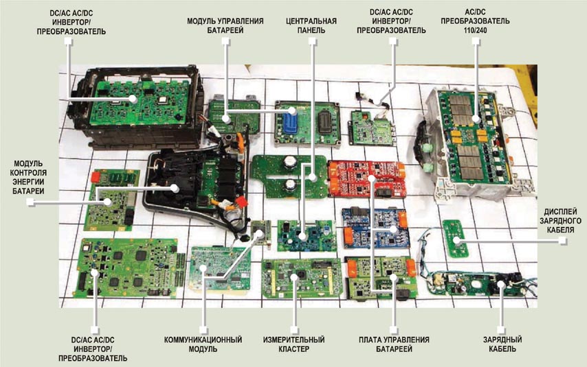
| Figure 5. | Of the 18 electronic modules in the Volt, roughly three-fourths handle hybrid-power-train functions (courtesy Munro & Associates). |
As customers gain experience, it will be interesting to see how – and how fast – this plug-in hybrid platform evolves in the coming years.
References
- DeMeis, Rick, “Innovation revelation: engineering the Chevy Volt,” EE Times, May 13, 2011, http://bit.ly/HJSyOx.
- DeMeis, Rick, “We tear down a Chevy Volt,” EE Times, March 12, 2012, http://bit.ly/HOpY0Y.
- DeMeis, Rick: “Driving impressions: Chevy Volt,” EE Times, Aug 2, 2011, http://bit.ly/tB3W3U.
Anatomy of an Automotive Teardown
Before beginning a teardown for Munro & Associates, Al Steier, senior associate at the company, reads all of the available information he can find on the car. For hybrid and electric vehicles, a basic step is to locate the service disconnect that makes the high-voltage lines safe when he removes it and then secure it in his toolbox. He takes photos, from all possible angles, of components before and after their removal for documentation and as part of the effort to fathom materials and manufacturing processes. Steier determines components and their makers at the PCB level. Capping off ICs and ASICs shows memory capacity if he cannot get this information from the components’ published data.
The Volt came to the teardown just like any other new car from a dealer – with a full tank of gas. The teardown team left systems on to drain the lithium-ion battery before taking apart the car, but the vehicle software started the gas engine to prevent deep discharge of the battery. The teardown team decided to drain the tank and then leave on the lights, radio, and other systems, draining the 12V battery. The high-voltage system recharged the battery overnight – the system software did not allow the battery to completely discharge – but only to a level at which the car could travel 35 miles. A company specializing in electric vehicles then drained the battery using a power resistor across the terminals.
Steier had previously taken apart a Toyota Prius hybrid and found some differences between the Prius and the Volt (Reference A). For example, as a plug-in vehicle, the Volt has an extra inverter module for charging. The Volt uses a lithium-ion battery, whereas the Prius uses a nickel-metal-hydride battery. For hybrid thermal management, the plug-in Volt uses liquid cooling, whereas the Prius features air cooling. Further, in supplying the electronic components, the Volt seems to have a more diverse supplier base; the Prius primarily uses Toyota technology.