Roger Allan
Electronic Design
An array of advances in thermal-management products and methodologies, some bordering on exotic, arm designers with essential weapons to battle the heat
As consumer demands for “smaller” and “faster” intensify, mammoth challenges emerge when it comes to beating the heat generated by ever-denser printed-circuit boards (PCBs). As stacked-up microprocessors and logic elements reach into the gigahertz range of operation, cost-effective thermal management becomes perhaps the highest priority among engineers in the design and packaging and materials fields.
Adding to those headaches is the current trend of manufacturing 3D ICs for greater functional densities. Simulations show that a 10 °C rise in temperature can double a 3D IC chip’s heat density, degrading performance by more than one-third.
Microprocessor Challenges
Projections by the International Technology Roadmap for Semiconductors (ITRS) show that within the next three years, interconnect wiring in difficult-to-cool regions of a microprocessor will consume up to 80% of the chip’s power. Thermal design power (TDP) is one measure to assess a microprocessor’s propensity to handle heat. It defines the upper point of the thermal profile as well as the associated case temperature.
The latest microprocessors from Intel and Advanced Micro Devices (AMD) feature TDPs ranging from 32 to 140 W. This number continues to rise in conjunction with increasing microprocessor operating frequencies.
Large data centers that employ hundreds of computer servers are particularly susceptible to heating problems. According to some estimates, the servers’ cooling fans – which draw up to 15% of the electrical power – actually become considerable heat sources in and of themselves. On top of that, the cost of cooling a data center can constitute about 40% to 45% of the center’s power consumption. All of these factors create a greater demand for local and remote temperature sensing and fan control.
The thermal-management challenge becomes trickier when it involves PCBs housing multicore processors. While each processor core in the array may dissipate less power (and thus less heat) than a single-core processor, the net effect on large computer servers is the addition of more heat dissipation to a data center’s computer system. Simply put, many more processor cores run for a given amount of PCB space.
Another thorny issue with IC thermal management concerns the appearance of hot spots on a chip’s package. Heat fluxes can climb as high as 1000 W/cm2, which is a condition that’s difficult to track.
PCBs play a critical role in thermal management, thus requiring a thermal design layout. Whenever possible, designers should keep power components as far away from each other as possible. Furthermore, they should be kept away from the PCB’s corners, which will help maximize the amount of PCB area around the power components to facilitate thermal dissipation.
It’s common for exposed power pads to be soldered to a PCB. Often, exposed-pad-type power pads conduct about 80% of the heat generated through the bottom of the IC package and into the PCB. The remaining heat dissipates through the package’s sides and leads.
Heat Helpers
Designers now can seek help via a number of improved heat-management products. They include heatsinks, heat pipes, and fans that allow for active and passive convection, radiation, and conduction cooling. Even the manner of the PCB-mounted chip’s interconnection helps mitigate heat problems.
For example, the common exposed-pad approach used for interconnecting an IC chip to a PCB may increase heat problems. When soldering the exposed path to a PCB, the heat travels quickly out of the package and into the board. The heat then dissipates through the board’s layers and into the surrounding air.
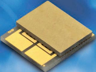
Thus, Texas Instruments (TI) devised a PowerPAD method that mounts the IC die to a metal plate (Fig. 1). This die pad, which supports the die during fabrication, serves as a good thermal heat path to remove the heat away from the chip.
 |
|
| Figure 1. | The die pad in Texas Instruments’ PowerPAD supports the die during fabrication, thus serving as a good thermal heat path to remove the heat away from the chip. |
According to Matt Romig, analog packaging product manager at TI, its PowerStack method is the first 3D packaging technology to stack high-side vertical MOSFETs. It combines both high-side and low-side MOSFETs held in place by copper clips and uses a ground potential exposed pad to provide thermal optimization (Fig. 2). Employing two copper clips to connect the input and output voltage pins results in a more integrated quad flat no-lead (QFN) package.
 |
|
| Figure 2. | TI’s PowerStack 3D packaging technology stacks high-side vertical MOSFETs. It combines both high-side and low-side MOSFETs held in place by copper clips and uses a ground potential exposed pad to provide thermal optimization. |
Heat management for power devices is an even greater challenge. Higher-frequency signal processing and the need to shrink package size are pushing conventional cooling techniques to the brink. Kaver Azar, president and CEO of Advanced Thermal Solutions, proposes the use of an embedded thin-film thermoelectric device that includes water-cooled microchannels.
Azar envisions one solution that minimizes spreading resistance, the largest resistance in the path of heat transfer, with a forced thermal spreader bonded directly to the microprocessor die (Fig 3).
 |
|
| Figure 3. | An embedded thin-film thermoelectric device proposed by Advanced Thermal Solutions uses water-cooled microchannels. A forced thermal spreader that’s bonded directly to the microprocessor die minimizes spreading resistance, the largest resistance in the path of heat transfer. (Source: “Cooling High-Power Packages,” Kaveh Azar, Advanced Packaging) |
This approach distributes the concentrated heat of a small microprocessor die to the larger base area of the heatsink, which transfers the heat to the ambient environment. Such a built-in forced thermal spreader combines micro and mini channels in the silicon package. The water flow rate inside the channels is approximately 0.5 to 1 liter/minute.
Simulation results showed that on a 10- by 10-mm die within a ball-grid-array (BGA) package, a 120- by 120-mm heatsink base-plate area yielded a thermal resistance of 0.055 K/W. Using a heatsink material with thermal conductivity equal to or higher than diamond yielded 0.030 K/W.
Paul Magill, vice president of marketing and business development for Nextreme Thermal Solutions, also suggests thermoelectric cooling, advocating that cooling should start at the chip level. The company offers localized thermal management deep inside electronic components using tiny thin-film thermoelectric (eTEC) structures known as thermal bumps (Fig. 4). The thermally active material is embedded into flip-chip interconnects (e.g., copper pillar solder bumps) for use in electronic packaging.
 |
|
| Figure 4. | Nextreme Thermal Solutions offers localized thermal management deep inside electronic components thanks to tiny thin-film thermoelectric (eTEC) structures known as thermal bumps. The thermally active material is embedded into flip-chip interconnects, such as copper pillar solder bumps, for electronic packaging. (Source: “Ensuring Optimal High-Power LED Performance With Thermal Management,” by Jon Domingo, Lumex, ECN, April 11, 2011) |
Localized cooling at the chip wafer, die, and package levels delivers important economic benefits. For instance, in a data center that employs hundreds and thousands of advanced microprocessors, it’s far more efficient than removing heat with more expensive and bulkier air-conditioning systems.
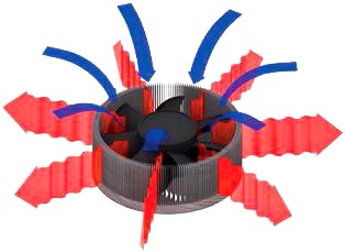
In some devices like LEDs, a combination of passive and active cooling techniques can improve device performance and lifetime (Fig. 5). For example, using a fan inside a heatsink often will reduce thermal resistance to 0.5 °C/W, which is a significant improvement over the typical 10 °C/W achieved with passive cooling (heatsinking) alone.
 |
|
| Figure 5. | In LEDs or similar devices, a combination of passive and active cooling techniques can boost performance and lifetime. For example, using a fan inside a heatsink often reduces thermal resistance to 0.5 °C/W, which is a considerably improvement over the typical 10 °C/W achieved with passive cooling (heatsinking) alone. |
Simulate And Simulate Again
Thermal control has always been, and continues to be, one of the limiting factors to achieving greater IC performance. With space at a premium in these ever-smaller ICs and their packages, there’s little or no room to help cool them. It has forced designers to consider exotic cooling techniques and new, evolving cooling materials.
Nonetheless, the basic premise remains: Designers must pay more attention to the science of thermodynamics for optimal cooling solutions. And the entire process should start with thermal analysis software – well before a design is put into production.
That’s where simulation software tools enter the picture. Products like the Mentor Graphics’ Flotherm 3D V.9 software tool help 3D IC designers quantify thermal quantities, enabling them to address thermal problems as they arise. This computational fluid-dynamics (CFD) product provides images of bottleneck (Bn) and shortcut (Sc) fields. As a result, engineers can identify where and why heat-flow congestion occurs in their designs.
According to Erich Bürgel, general manager of Mentor Graphics’ mechanical analysis division, innovative Bn fields show where a design’s heat path is being congested as it attempts to flow from high-junction temperature points to the ambient point. The Sc fields highlight possible approaches to create a new effective heat-flow path by adding a simple element such as a gap pad or a chassis extrusion.
Flotherm 3D V.9 supports the importing of XML model and geometry data to enable the software’s integration into data flows. It also has a direct interface to Mentor Graphics’ Expedition PCB design platform. As a result, users can add, edit, or delete objects such as heatsinks, thermal vias, board cutouts, and electromagnetic cans for more accurate thermal modeling.
With thermal simulation, designers can accurately predict the thermal performance of the initial and subsequent designs without having to build and test a prototype. Design variables such as the number of heatsink fins, fin thickness, heatsink base thickness, and thermal resistance of the thermal-interface materials should be considered.
Proper thermal models are essential for future 3D ICs that plan to use stacked logic and memory devices consisting of thin die, which strongly reduces lateral heat spreading.
As a die’s thickness shrinks, higher-temperature spots become more common. Hot spots on the logic die cause local temperature increases in the memory die, possibly reducing DRAM retention time.
Researchers at Belgium’s Interuniversity Micro Electronics Center (IMEC) have already proven correct thermal models for the design of next-generation 3D mixed-stack ICs. These 3D stacks, which closely resemble commercial chips of the future, consist of IMEC proprietary logic CMOS ICs stacked on top of commercially available DRAMs. Stacking is accomplished with through-silicon vias (TSVs) and micro-bumps. The research was a collaborative effort between IMEC and partners Amkor, Fujitsu, Globalfoundries, Intel, Micron, Panasonic, Qualcomm, Samsung, Sony, and TSMC.
IBM plans to use microchannel water cooling for its future 3D IC processors, such as the Power8 processor scheduled for introduction in 2013 (Fig. 6). Bruno Michel, manager of the Advanced Thermal Packaging Group for IBM’s Zurich, Switzerland research facility, says that energy-efficient, hot-water cooling technology is part of IBM’s concept of a zero-emissions data center. To cool 3D chip stacks, which generate more heat than a single processor in nearly the same space, water rather than air was used to reduce energy consumption.
 |
|
| Figure 6. | IBM plans to use microchannel hot-water cooling for future 3D IC processors, such as the Power8 processor due to arrive in 2013. |
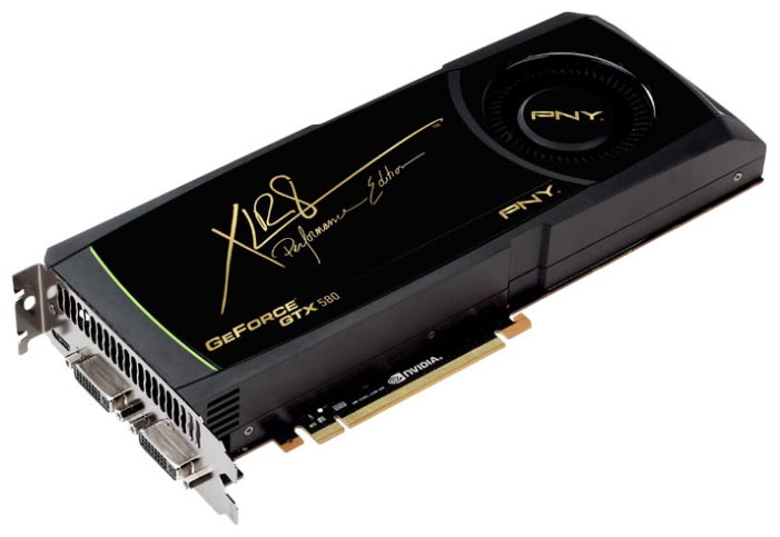
Liquid cooling of CPUs is also performed in the XLR8 GTX 580 GeForce graphics card from PNY Technologies, which addresses challenging graphics-intensive gaming products. PNY and Asetek, a specialist in CPU thermal management, joined forces to produce a product for gaming enthusiasts and their GPU/CPU cooling systems.
Engineered with a closed-loop system and built with Asetek’s sealed water cooler already attached, the combination design offers consumers an out-of-the-box, ready-to-install product that costs $649.99 (Fig. 7). PNY claims the new system offers up to 30% cooler temperatures, quieter acoustics, and faster performance than the standard-reference-designed Nvidia GeForce GTX 580 graphics card.
 |
|
| Figure 7. | The XLR8 GTX 580 GeForce graphics card from PNY Technologies. |
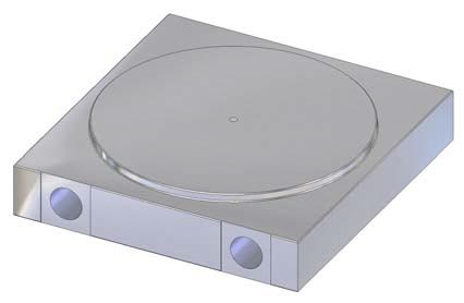
Thermal management via water cooling also is employed in a wide variety of power devices – thyristors, MOSFETs, and silicon-controlled rectifiers (SCRs) are just a few. One example is the XW180GC34A/B developed by Westcode Semiconductors Ltd., a subsidiary of Ixys Corp. (Fig. 8). The nickel-plated heatsink has a 127-mm diameter contact plate, suiting it for press-pack devices with electrode contacts up to 125 mm in diameter.
 |
|
| Figure 8. | Westcode Semiconductors’ Water Cooler XW180GC34. |
Typical heatsink to input water thermal resistance, for flow rates of 10 L/min., is 4.3 K/kW (two coolers plus one semiconductor device) and 5.6 K/kW (three coolers plus two semiconductor devices). The heatsink comes with or without an integral connecting bus bar.
“Typical applications for the coolers would be mini megawatt-power-level devices and high-power rectifiers, as in heavy industrial applications, or for electric train trackside substations, as well as in applications in electricity generation and distribution,” says Frank Wakeman, Westcode’s marketing and technical support manager. “The high-efficiency cooling provided with these coolers enables customers to achieve high-power density in their systems with much reduced footprint.”