To transfer maximum power from a circuit to a load, the load’s resistance, RL, must match the source resistance, RO (Fig. 1). In the case of a complex load, ZL, and a resistive source, this transfer can require the use of a bulky inductor. This idea shows how to replace the physical inductor with a smaller synthesized inductor.
 |
||
| Figure 1. | The simplest matching circuit consists of a resistive load, RL, equal to the source resistance, RO. |
|
A good example of a complex load is a piezoelectric transducer represented by the Butterworth - Van Dyke model as CO, RL, CS, and L (Fig. 2a). At series resonance, the load impedance reduces to the equivalent circuit shown in Figure 2b. The load is still complex, with RL in parallel with CO. This makes matching to RO impossible without a complex conjugate match of –CO at the source — that is, an inductor in parallel with CO and having the same magnitude of reactance (Fig. 2c).
|
||||||||
| Figure 2. | An example of a complex load is a Butterworth-Van Dyke model of a piezoelectric transducer (a), which can be reduced to an equivalent circuit (b). To match the load to the source, an appropriate inductor, L, must be added (c). |
|||||||
To match RO to RL, L must be chosen to “resonate out” CO:
–XCO = XL,
or
Therefore:
where w = 2pf.
 |
||
| Figure 3. | Instead of a bulky physical inductor, the designer can use this gyrator circuit, which provides a simulated inductance equal to (R1)(R)(C). |
|
To replace the physical inductor, L, with a synthesized inductor, consider the gyrator circuit, which Bernard Tellegen invented in 1948 (Fig. 3). The circuit is basically a differentiator in which the operation of capacitor C is reversed. The simulated inductance becomes:
L = (R1)(R)(C) [Henries].
 |
||
| Figure 4. | In a typical implementation of the gyrator matching circuit, dynamically varying R can change the tuning of the circuit for different complex loads, provided that the voltage across the load is measured to ensure optimum tuning. |
|
Typically, R1 is kept to 100 W or less so the circuit’s Q can be at least 10. (Details of the gyrator circuit are available on the Internet. Figure 4 shows the final implementation of the matched circuit. With this circuit, R can be dynamically varied to change the tuning on the fly for different complex loads, provided that the voltage across the load is measured so optimum tuning can be achieved.
 |
||
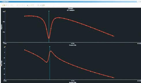
| Figure 5. | In these simulation results, the voltage across the load (top trace) shows a minima at the resonant frequency. The phase of the voltage across the load (bottom trace) is 0° at resonance. These results indicate the selected inductance created a successful match. |
|
Figure 5 shows the simulation results of a tuned circuit using the described gyrator circuit. The top trace is the voltage across the load, which shows a minima at the resonant frequency. The bottom trace shows the phase of the voltage across the load, which is 0° at resonance. These results indicate that the selected synthesized inductance successfully matches the load to the source.