My home has numerous LED bulbs, be them in recessed fixtures, hanging fixtures, and standing lamps. So far two have failed. The first was a BR30 that cycled on an off with temperature, the second was a A19 bulb that gave off far too few lumens. Both are manufactured in China, sold by Feit Electric, and purchased from Costco.
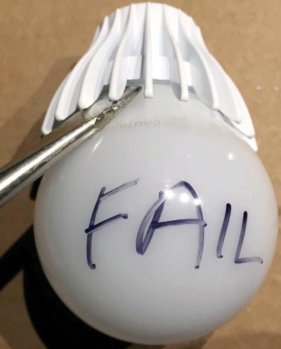
Reaching the power circuit of this bulb required destroying the base, nothing you can't do with a screwdriver and a wire cutter. Figure 1 shows how to pry off the "glass" from the heat sink.
 |
||
| Figure 1. | A screwdriver separated the bulbs plastic "glass" from the heat sink. |
|
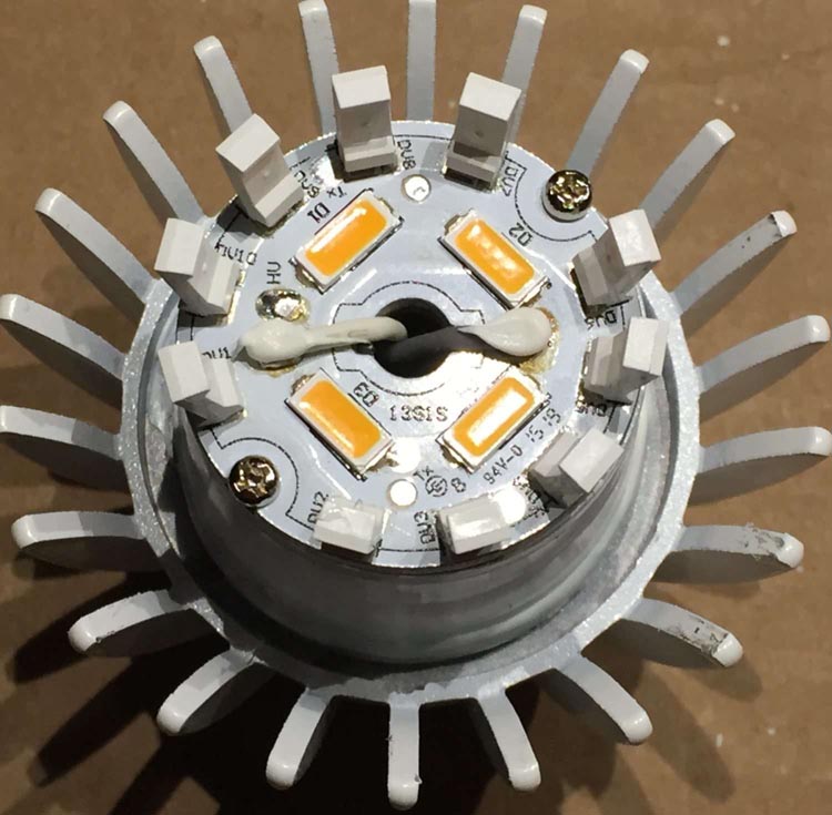
With the glass removed, you can see 14 LEDs in Figure 2. Note how 10 of them are vertical mounted. That's how the bulb's emitted light becomes "omnidirectional."
 |
||
| Figure 2. | Fourteen LEDs emit light in a more-or-less omnidirectional pattern. |
|
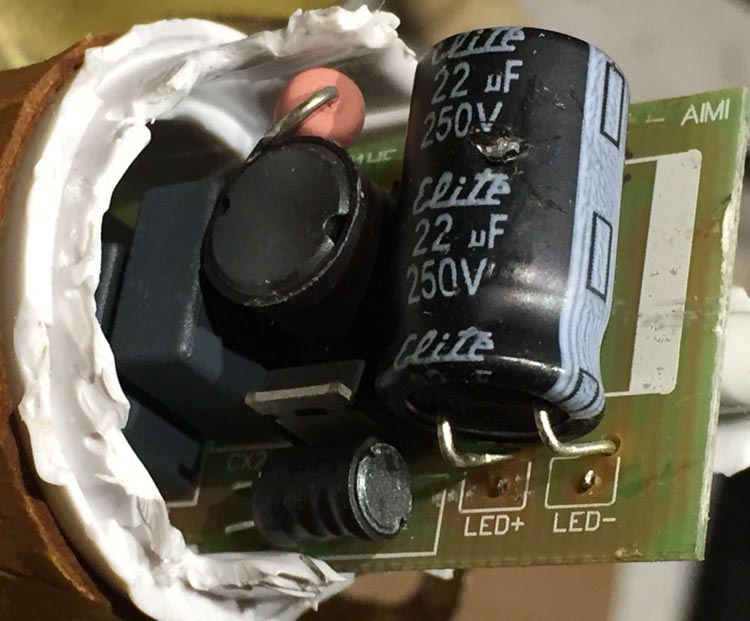
With the LED board removed, the PCB was visible but not accessible (Figure 3). Using a wire cutter, I nibbled away the plastic base, which revealed the board. Note the 250 V aluminum electrolytic capacitor across the output to the LEDs. Aluminum electrolytic capacitor? They just fail. How can this LED bulb possibly last 25,000 hours? The apparent damage on the capacitor is superficial, caused when opening the bulb housing.
 |
||
| Figure 3. | The power-supply board inside the LED uses a 250 V electrolytic capacitor across the LED drive voltage. |
|
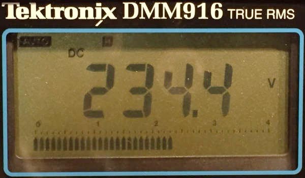
Before I proceeded with the teardown, I measured the voltage at the output with a DMM. The bulb's base was still intact at this point so I inserted it into a lamp fixture. The output was a surprising 234 VDC unloaded (Figure 4). There's no transformer on the board, hence no isolation of AC mains.
 |
||
| Figure 4. | The power board's output voltage was over 234 VDC unloaded. I didn’t expect that. |
|
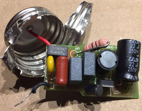
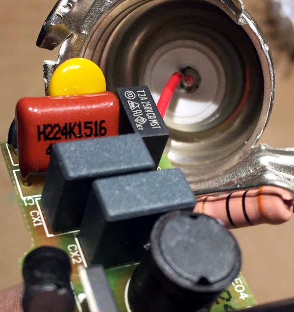
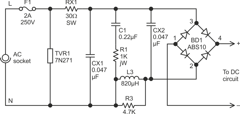
Next, it was time to completely remove the board. That meant destroying the rest of the bulb. Now, let's take a tour of the components. Figure 5 shows a 2 A, 250 V fuse in series with the AC line hot and neutral lines. The mustard-colored component on the left is TVR1, a 7N721K 270 V varistor.
 |
||
| Figure 5. | Circuit protection starts with a 2 A, 250 V fuse (F1). A 30 Ω, 1/2 W resistor (RX1) is clearly visible. |
|
By bending the components, their markings became visible. Figure 6 shows C1, a 0.22 µF capacitor. The black canister at the bottom of the photo is an unmarked inductor designated L1.
 |
||
| Figure 6. | A 0.22 µF capacitor, designated C1. | |
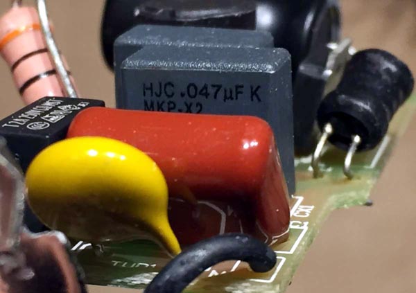
Figure 7 shows capacitors CX1 and CX2, both of which are 0.047 µF.
 |
||
| Figure 7. | Capacitors CX1 and CX2 are both 0.047 µF. | |
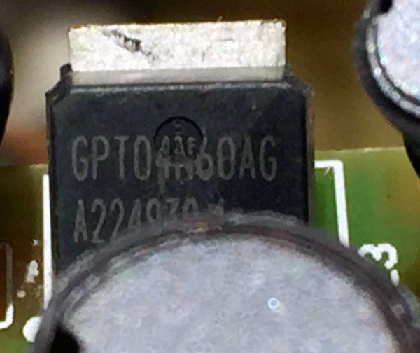
Figure 8 shows Q1, a 4N60 N-channel MOSFET.
 |
||
| Figure 8. | A 4N60 N-Channel MOSFET, designated as Q1. | |
While inductor L1 has no markings, inductor L2 is marked 821, indicating a value of 820 µH (Figure 9).
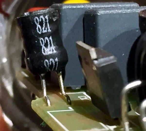 |
||
| Figure 9. | Inductor L2, 820 µH. | |
The underside of the board (Figure 10) contains three active components. BD1 is a full-wave rectifier marked ABS10 from Taiwan Semiconductor. Maximum voltage is 70 VRMS.
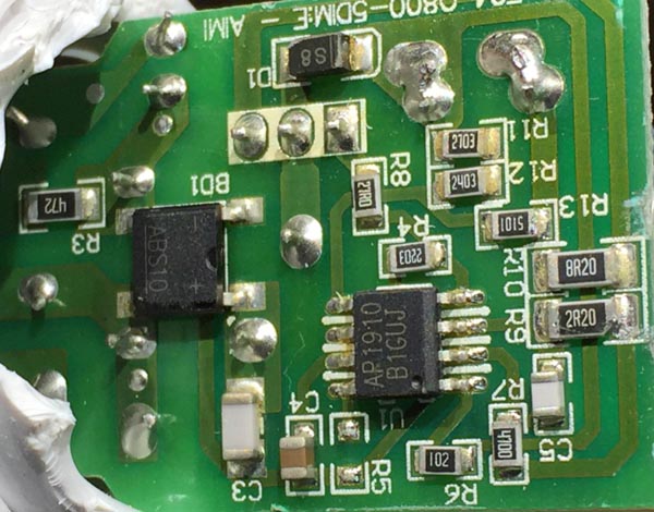 |
||
| Figure 10. | The underside of the board holds an ABS10 full-wave rectifier, an RB751 low-voltage drop diode, and an AP1910 LED driver controller. |
|
Component D1 is an RB751V low-forward-voltage diode used to drive the LEDs. Finally, there's U1, an AP1910 Universal High Brightness LED Driver Controller. Figure 11 shows the block diagram.
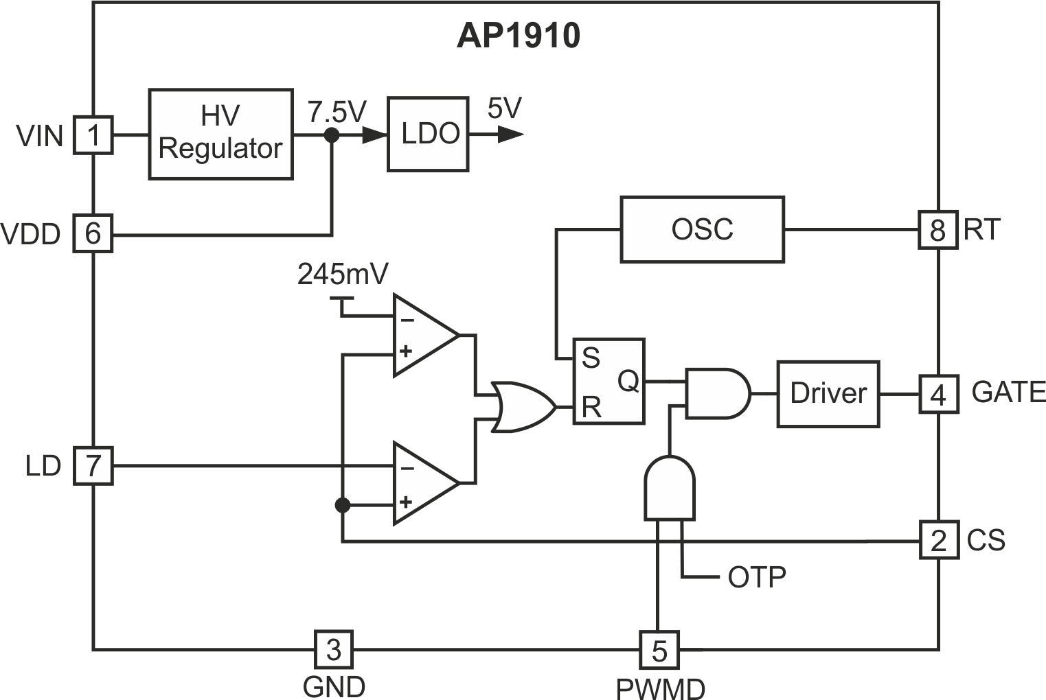 |
||
| Figure 11. | The AP1910 LED controller controls LED brightness with N-channel MOSFET Q1. |
|
Figure 12 shows the AC side of the power circuit. F1 and TVR1 provide circuit protection against overvoltage and overcurrent. That's comforting. Too bad fake iPhone chargers don't protect themselves from overvoltage or overcurrent.
 |
||
| Figure 12. | The AC side of the power circuit has circuit protection, filtering, and a full-wave rectifier. |
|
On the DC side (Figure 13), U1 and Q1 control the LED brightness using pulse-width modulation to attain a constant current. Inductor L1 and capacitor C3 store energy during an off cycle.
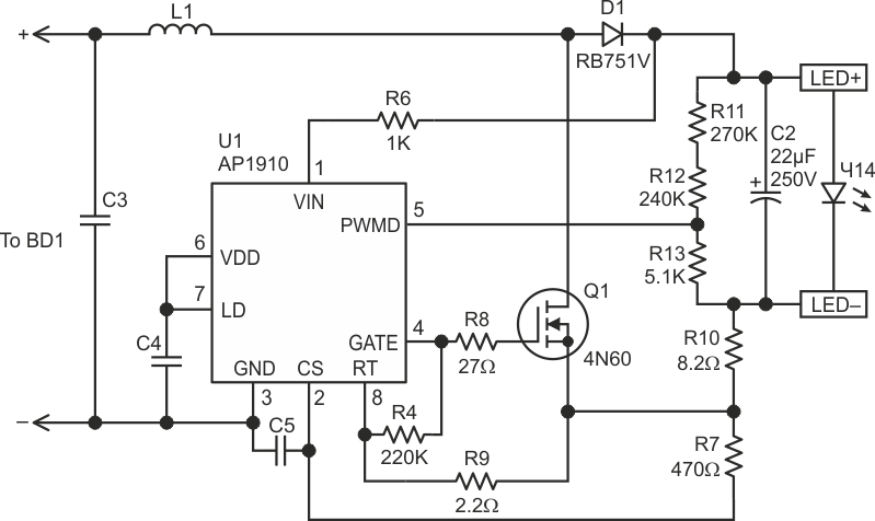 |
||
| Figure 13. | The DC side of the power circuit contains the LED drive controller U1 that drives an N-channel MOSFET Q1. |
|
Now we see what's inside this LED bulb. In a comment from LED lamp cycles on and off, why?, Brett_cgb was right in his assumption that there is no isolation. I must admit my surprise of seeing no isolation from AC mains and that the LED array was driven by 234 VDC. Given that measurement, I have to assume that the DC voltage across the LED array wasn't the cause of the bulb's low light intensity compared to the other Feit Electric A19 LEDs used around the house.