I began my career in electronic circuit design in 1972; I remember what relatively few integrated circuits were available at that time. So, when I look back at the Apollo program that began in the early '60s and put a man on the Moon in 1969, I am in awe of the creative use of that era’s technology put to use in that spacecraft system, using mostly discrete transistors and discrete logic gates to perform communication, guidance, and more on the journey to the Moon.
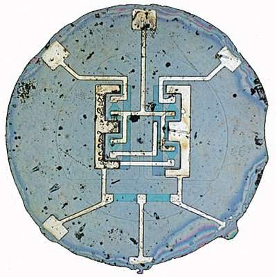
The first group of spacecraft in NASA’s Mercury series, which were launched in the late 1950s, had no computers on them at all. At that time, Jack Kilby, from Texas Instruments, had invented the first integrated circuit (IC) in September 1958; it used external wire connections. In 1959, Robert Noyce, from Fairchild Semiconductor, invented the "monolithic circuit," which put all the components on silicon chip and connected them with copper lines printed on an oxide layer – the first microchip.
 |
||
| The first type ‘F’ flip-flop fit into a TO-18 can. (Image courtesy of Fairchild Camera & Instrument Corp. and the Computer History Museum.) |
||
In 1961, the first practical commercial IC, the NOR Gate (made with three transistors and a load impedance into a TO-5 ‘can’ with 6 connection legs) was developed.
 |
||
| Most of the electronics on Apollo were composed of transistor circuitry (SC is the spacecraft, SCS is stabilization and control system, and CMC is the command module computer.) |
||
![Logic circuitry mostly used micrologic [1] (µLogic) ICs. (NAA is North American Aviation).](https://www.rlocman.ru/i/Image/2019/05/05/Fig_3.gif) |
||
| Logic circuitry mostly used micrologic [1] (µLogic) ICs. (NAA is North American Aviation). | ||
The Apollo program was a major factor in the growth of Silicon Valley in California in the early 60s.
The Apollo Guidance Computer (AGC)
In order to achieve President Kennedy’s goal of putting a man on the Moon by the end of the 1960s, new technologies would be required. A prime need was for a small, lightweight guidance and navigation unit that could process complex trajectory equations and issue guidance commands to the Apollo spacecraft in ‘real-time’ during the flight. The AGC was created.
 |
||
| The AGC physical configuration. (Image courtesy of NASA Archives “Apollo Guidance and Navigation System: Equipment and Familiarization Manual”). |
||
In August 1961, NASA gave the opportunity of designing the AGC to engineers at the Massachusetts Institute of Technology (MIT). Those engineers began designing the first computer to go into space on the Apollo program. They needed to reduce the size and weight of that on-board computer and the emergence of the IC became the means to achieve that task by replacing many, many discrete transistors. The Apollo computer used few flip-flop registers due to size and weight considerations; however, seven key registers in the computer did use flip-flops.
It was 1962 when MIT became the first to use these new integrated circuits, introduced in 1961, in their AGC design because it would lead to that necessary lightweight compact unit. In 1963, MIT was testing and developing the AGC Block I units. They ordered about 60% of the world's available ICs at that time!
MIT's original AGC design called for only 4K words of fixed memory and 256 words of erasable (at the time, two computers for redundancy were still under consideration). In June 1963, the figures had grown to 10K of fixed and 1K of erasable. The next design jump was to 12K of fixed, and MIT was still insisting that the memory requirement for an autonomous lunar mission could be kept under 16K! Fixed memory jumped to 24K and then finally to 36K words, and erasable memory had a final configuration of 2K words.
The AGC system was built by Raytheon, and each system used about 4,000 "Type-G" (3-input NOR gate) circuits. They acquired 200,000 units at $20-30 each; the AGC was the largest user of ICs through 1965.
The Lunar Module (LM) weight and power requirements made an amplitron-tube design more attractive than the traveling-wave-tube design used in the Command Service Module (CSM). The amplitron-tube power amplifier weighed 16.8 pounds and required 72 watts; the CSM power amplifier weighed 32 pounds and required 90 or 167 watts, depending on mode selection.
The CW Amplitron was a continuous-cathode, crossed-field, backward-wave amplifier. This device had many characteristics in addition to high efficiency that made it perfect for space telemetry.
The CW S-band power amplifier
The QKS997 Amplitron (crossed-field amplifier), a 25-watt CW S-band amplifier had a 20 db gain and greater than 50% efficiency. A unique RF circuit design was employed which permitted near minimum magnet weight and convenient conduction cooling. Low residual phase modulation, insensitivity to environmental conditions, low transmission loss in the off condition, weight close to 1 pound, and cathode loading compatible with long life were other positive features of the design. This power amplifier (PA) did have numerous corona problems, which occurred at critical pressure (the AC and RF coronas self-extinguished, but the DC arc in the high-voltage module and the DC arc in the potted high-voltage power supply were destructive); these were all eliminated by improved design and manufacturing techniques. Ultimately, pressurization of the PA turned out to be the best way to eliminate any corona.
Integrated circuits and their failures on the PA
This was the early days of the integrated circuit: A failure that occurred in the steerable antenna during second-tier vendor testing was attributed to a µA702, an integrated circuit op amp developed by Bob Widlar. During the failure analysis, an internal aluminum lead wire that had opened because of corrosion was located. Further tests and analyses indicated that the problem was limited to the integrated circuits in glass flatpacks with aluminum internal leads (µA702 and µA710 comparator).
The following two failure mechanisms were occurring.
- Aqueous corrosion was caused by contaminant on the wires and moisture that either was entering the package through a leak or was being sealed within the package. Further analysis indicated that the sealing of moisture within the package was improbable.
- Glass-splattering that occurred when the glass-to-metal seal was made accounted for the contamination seen in some of the integrated circuits. This reaction between the glass and the aluminum inside the integrated circuit occurred with no additional outside factors. These failures began with integrated circuits bonded after March 22, 1967, and continued through final manufacture of that type of circuit in 1969.
Because of the extensive use of the µA702 integrated circuit throughout the LM, an ad hoc team was established to make a comprehensive review of pertinent data. This team made the following determinations:
- 12 corrosion-induced failures occurred in the vendor's stock of 2246 integrated circuits, which had an average shelf life of 0.8 years. The failure rate was 0.75 failure/million hours.
- Of the 421 integrated circuits (installed in the LM), which had an average age of 1.6 years, no corrosion-induced failures occurred. One failure was assumed, and the resultant failure rate was 0.17 failure/million hours. The installed integrated circuits had a lower failure rate because they were protected from handling and were conformal coated or potted; thus, a moisture barrier was provided. The circuits at the vendor had been subjected to environments designed to accelerate the failure rate and had received additional handling during tests.
Based on this information, the failure rate for assembled hardware was designated as h = 0.17 failure/million hours. This failure rate was deemed acceptable for parts of this type.
Apollo crew member interface with the AGC
The Command Module located the AGC in a lower bay near the navigator’s station. AGC (Block II) size was 24×6” and weighed 70.1 pounds. It used 70 W of power at 28 VDC. The AGC in the LM was exactly the same.
Apollo crew members would communicate with the AGC via display and keyboard systems (DSKY or ‘disky’ in NASA-speak). There were two DSKYs in the CM, one on the main control panel and one close to the optical instruments at the navigator’s station.
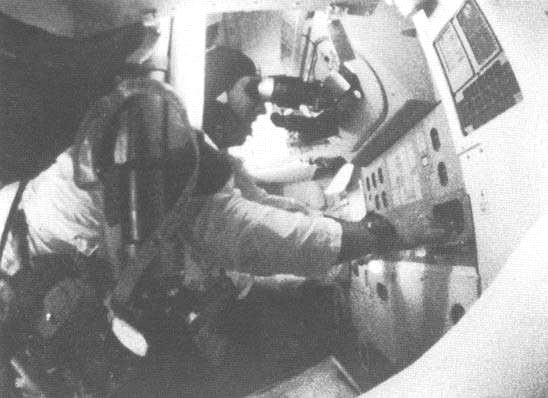
There was also a ‘mark’ button at the navigator’s station that would signal the AGC when a star fix was being taken. The navigator would look through the sextant device, called the alignment optical telescope, find a suitable navigation star and, with the help of the AGC, verify the guidance platform's alignment. The guidance and navigation subsystem gives astronauts the ability to navigate the spacecraft on a required course through space. It can be operated either semi-automatically or manually and performs the basic functions of guidance and navigation, similar to the navigation of an airplane or of a ship at sea.
 |
||
| Apollo astronaut James A. Lovell is seen here at the navigator’s station taking a star sighting on the Apollo 8 mission. (Image courtesy of NASA). |
||
There is always a ‘Plan B’ navigation system [5] with a traditional, manual sextant on board Apollo. Even the International Space Station (ISS) and the Orion spacecraft going to Mars will have a manual sextant on board and the astronauts can use it just as ancient sailors did on the high seas many years ago before electronics and modern technology.
Ultimately, we managed to send men to the Moon and back safely with basic electronic designs and a work ethic to fulfill President Kennedy's goal of landing a man on the Moon, and they did it with astronaut safety concerns in everything they designed. This year we celebrate the 50th anniversary of Neil Armstrong and his team setting foot on the Moon. What an incredible accomplishment for technology!
References
- Making Micrologic: The Development of the Planar IC at Fairchild Semiconductor, 1957–1963, David A. Laws, Michael Riordan, IEEE Annals of the History of Computing, IEEE 2012
- Apollo Guidance Computer and the First Silicon Chips, Paul Ceruzzi, Space History Department, Smithsonian Institution
- Integrated Circuits in the Apollo Guidance Computer, klabs.org
- Computers in Spaceflight: The NASA Experience, NASA
- The Story of the Apollo Sextant, Doug Adler, Astronomy.com