Richtek Technology
With huge choice of LED lamps available nowadays, it is not always easy to select the best suitable lamp for your living room or workspace. The light quality of LED lamps can vary greatly depending on the lamp design topology and choice of key components. AC line related light flicker usually varies at double the line frequency (100 Hz or 120 Hz) and is not easily noticed by most individuals. But light flicker at higher intensity and deep modulation can cause irritation, eye fatigue or headaches. When shooting videos, ambient light flicker will cause annoying interference patterns in the recorded video.
Light flicker in LED lamps is caused by the varying current that passes through the LED string. The relation of luminous flux versus current is not entirely linear; it depends on the LED string characteristic as shown in figure 1.
 |
||
| Figure 1. | The luminous flux of the LED string vs. current. | |
Measuring the varying current in the LED string is therefore not as accurate as measuring the actual light.
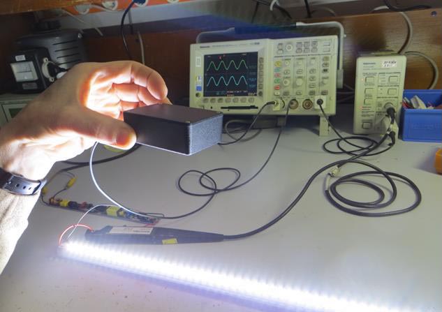
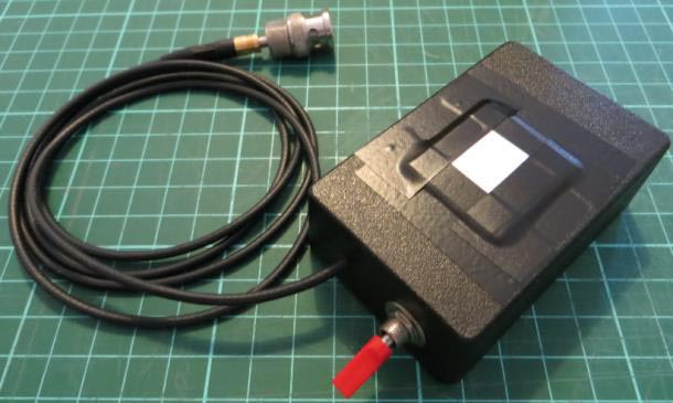
It is not too difficult to make your own light measuring tool from readily available components. Figure 2 shows a T8 LED lamp flicker measurement. The black box contains a light to voltage converter and its output waveform is shown on an oscilloscope. The waveform can be examined and light flicker % can be calculated.
 |
||
| Figure 2. | T8 lamp flicker measurement. | |
How to build the light sensor
The schematic in figure 3 shows a simple light to voltage converter using the TSL257 IC.
 |
||
| Figure 3. | Light to voltage converter circuit based on TSL257. | |
The TSL257 is a simple light to voltage converter IC with good linearity. It can be powered from a single Li-Ion cell, making it a portable measurement tool. The output voltage is directly proportional to the light intensity (irradiation) and can be connected to an oscilloscope, thereby showing the light fluctuation as a waveform on the scope screen. The 2 kHz bandwidth is sufficient for light flicker measurements. TSL257 is not expensive, and can be bought at Farnell or Digikey.
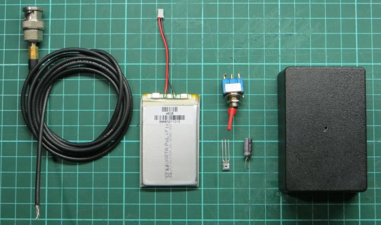
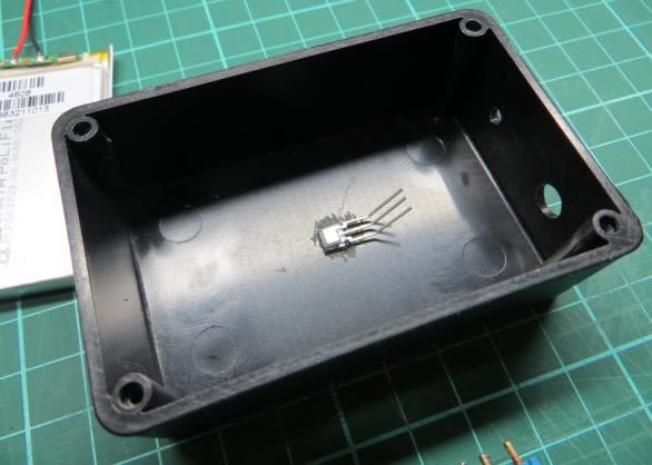
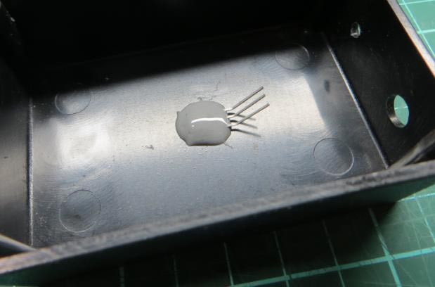
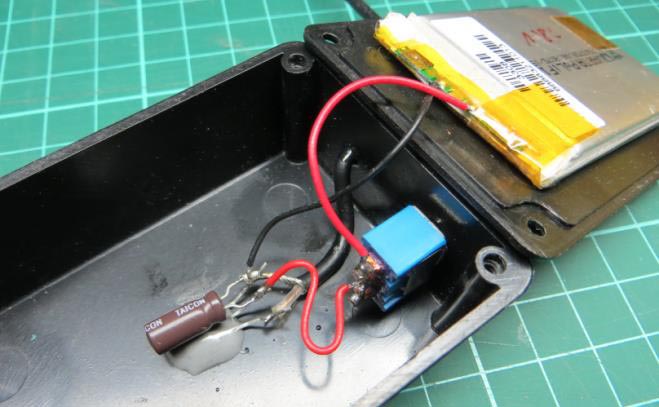
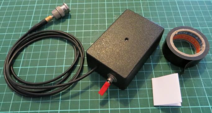
The group of photos in Figure 4 show how to build such a tool.
Required components:
- Li-Ion battery
- TSL257 IC
- a switch
- a 22 μF/25 V electrolytic capacitor
- black plastic box with a 3 mm hole drilled in the top.
The TSL257 is placed with the sensor towards the hole.
Then the sensor is fixed with non-transparent epoxy glue. Finally the other components are connected.
Due to the high light sensitivity of the TSL257, the incoming light to the sensor needs to be attenuated considerably to make it suitable to for measuring direct light from LED strings. Several layers of A4 paper can be placed over the hole to achieve sufficient light attenuation. For the test tool, 8 layers of paper were used.
|
||||||||
| Figure 4. | Assembly stages of light measuring tool. | |||||||
To avoid ambient light influence, the room lights should be switched off. The tool should be positioned above the LED light to achieve a light output reading with the maximum level around 3 V. When waveform clipping occurs, the distance to the light should be increased, or more layers of paper should be added for more light attenuation.
Measure the peak-peak and average value of the sensor output. Apply some averaging for noise reduction. For sine wave signals, the % flicker can be calculated from:

If the light flicker waveform is not sine shaped, the % flicker can be calculated according:

Figure 5 shows some examples of flicker measurements of LED candle lamps. The blue waveform is the mains voltage and the purple waveform is the measured light intensity. As can be seen, the light flicker can vary considerably over different lamps.
 |
||
| Figure 5. | LED candle lamps flicker measurement examples. 0% flicker 100% flicker 4.5% flicker 62% flicker |
|