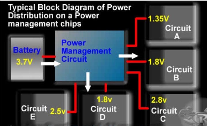
Integrated circuit (IC) power is responsible for controlling, managing, providing, and distributing source voltage to electrical circuits as well as other ICs in the circuit.
Basically, power ICs have the function of converting, stabilizing, and regulating the current and voltage through them according to a certain parameter. They are capable of dividing and multiplying many different types of voltages from a power source into the desired voltages according to usage requirements.
An example: You have a power source with a voltage of 3.7 VDC while other circuits only require a voltage of 1.8 V, then the 1.8 V value will be the value converted by the power IC.
What is LM317?
IC LM317 is a monolithic integrated circuit used for voltage regulation. The output current is up to 1.5 A and the output voltage range is adjustable over the range of 1.2 to 37 V, so the IC LM 317 is a pretty handy converter.
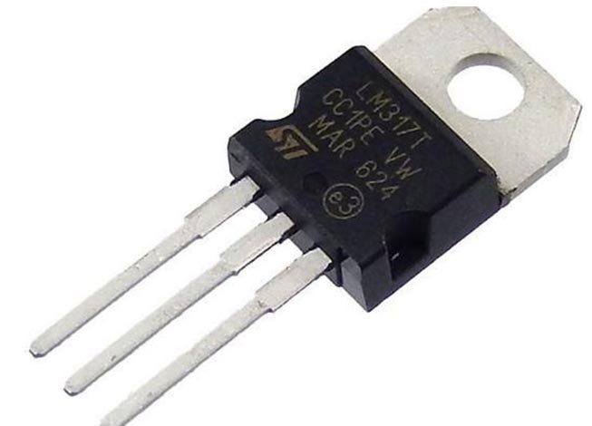 |
| LM317 is a linear voltage regulator IC widespread presence in the devices and electronic circuits. |
IC LM317 has outstanding advantages over the 78xx line in that we have the ability to adjust the output voltage through the external resistor in the circuit.
One of the drawbacks that needs to be noted is the heat generating so high. Therefore, with the circuits using this type of IC need to maintain a moderate temperature, it’s better with a cooling fan.
How to make a voltage adjustable mini power supply from IC LM317
To help you more understanding about operation principle of IC and especially is IC LM317 in practice. Now we will guide you on how to make a voltage adjustable mini power supply from IC LM317.
Firstly, prepare necessary components to make a voltage adjustable mini power supply, include:
- 9 V. Transformer
- IC LM317
- heat sink
- 4 diodes 1N4007
- 1K resistor
- 10K potentiometer
- 3 V led + 680 Ohm resistor
- 16 V-470 uF capacitor
- Two Alligator clips , 2 Banana Jacks , one switch
- mini voltmeter 3.5-30 V
- Power cord
- Hardcover (you can use wood or foam instead)
- 2 pieces of size 15×8 (cm)
- 2 pieces size 15×5 (cm)
- 2 pieces size 7.5×5 (cm)
Next, There is instruction to connect the mini power from IC LM317
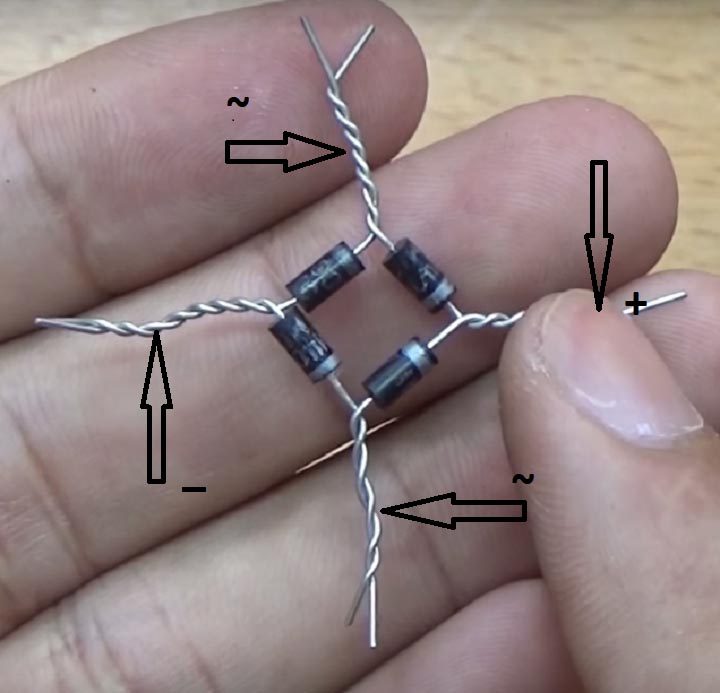
Step 1: Make a diode bridge from 1N4007 diode
Using 4 1N4007 diodes connected in a “bridge” configuration that converts the AC voltage from the secondary of the transformer into DC voltage.
You connect the diode bridge as shown.
 |
| Diode bridge. |
Note: After connecting, pay attention to determine the electrodes of the diode bridge.
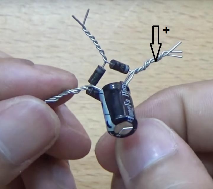
Step 2: Connect the capacitor to the diode bridge.
You connect the positive electrode of the capacitor to the positive electrode of the diode and the negative electrode of the capacitor to the negative electrode of the diode.
 |
| Diode bridge and Capacitor. |
Note: Distinguish the electrodes of the capacitor.
- The negative pin has a (-) sign on the capacitor
- The positive pin has a (+) sign and is longer
Step 3: Connect the two AC electrodes of the diode bridge to the two electrodes of the secondary of the transformer.
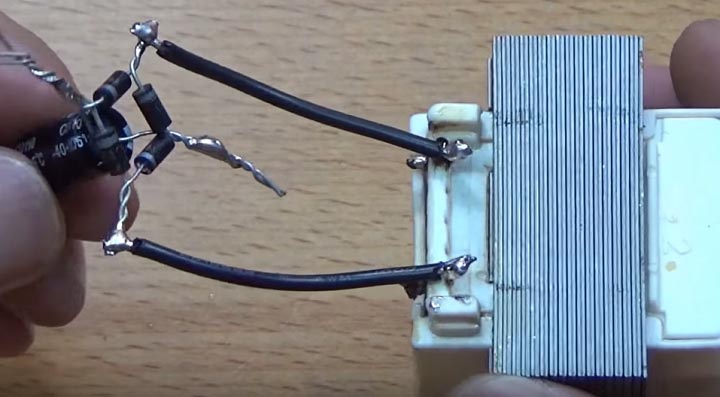 |
| Connect diode bridge to transformer. |
Step 4: Attach IC LM317 to the heatsink.
Note: Apply thermal paste carefully before attaching the IC LM317 to the aluminum heatsink
Step 5: Solder 1K resistors to pins 1 and 2 (an outer and middle pin) of IC LM317.
Step 6: Use solder wire for pin 3 (the outermost pin) of the IC to electrode (+) of the diode bridge.
Step 7: Connect the positive electrode of the voltmeter to pin 2 of the IC LM317 in series with the female banana jack.
Step 8: Connect the negative electrode of the diode bridge to the negative electrode of the voltmeter and the other female banana jack.
Step 9: Use the solder wire on foot 1 of the potentiometer (external pin) with the (-) electrode of the diode bridge.
Step 10: Connect the middle pin of the potentiometer to pin 1 of IC LM317
Step 11: Solder the 680 resistor to the positive pin of the led and solder it to the positive pin of the diode bridge. Solder the negative electrode of the LED indicator to the negative electrode of the diode bridge.
Step 12 : Make a box for the power supply from cardboard
You assemble the container as shown in the picture
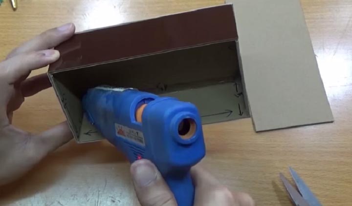 |
| Container Box. |
Step 13: Drill a hole in the wall of the box to thread the wire inside. Solder the power supply wire to the primary of the transformer
Step 14: Connect the switch to the primary electrode of the transformer
Step 15: Arrange and fix the components in the container
Then mount the transformer near the input wiring hole
Note: Don’t forget to apply glue to the junction at the primary electrode
- Then arrange the diode bridge and IC
- Drill a hole in the middle to mount the potentiometer
Note: Prepare the knob for the potentiometer
- Attach two female banana jacks
- Mount the led, voltmeter and switch on the lid of the container
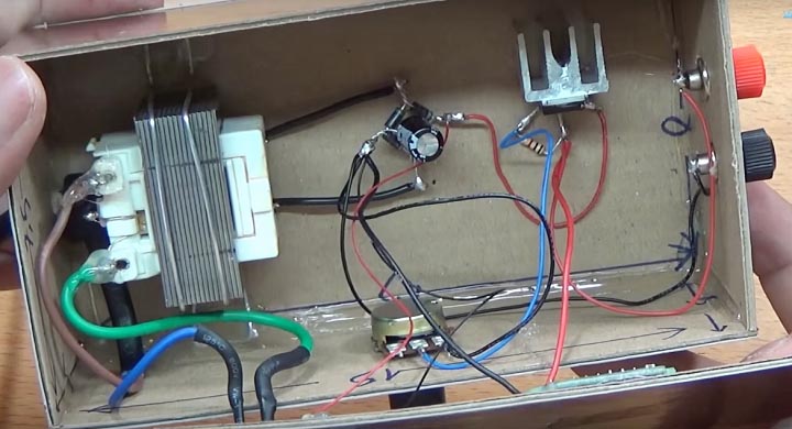 |
| Installation diagram of mini power supply. |
Step 16 : Connect the male banana jack and the alligator clip and plug it into the male banana jacks
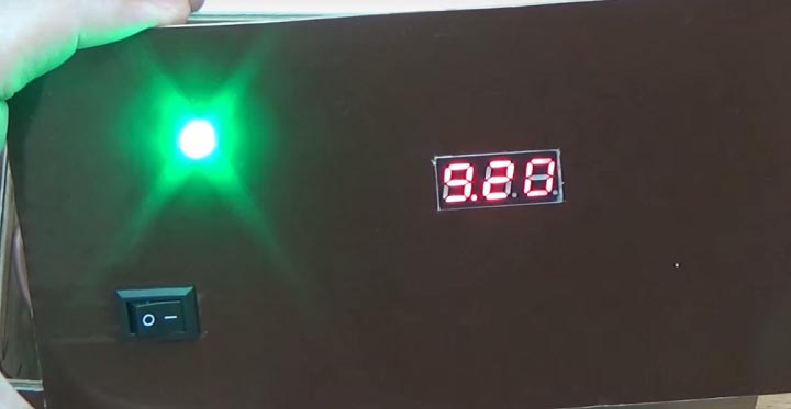
Finally, we have the completed mini power supply from IC LM317 as below.
To summarize, IC (Integrated circuit) power has a lot of applications. Nowadays, we have a lot of choices for IC power but IC LM317 seems to be the most common in the field.
Above are some of our IC knowledge that we hope will help a little with your question.