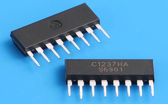
This is just an ultra-quick blog post about a nostalgic IC: µPC1237. It’s a timeless bipolar analog IC from NEC designed for protecting stereo audio power amplifiers and loudspeakers. I used to see this awesome chip all the time in the 1990s, and I am surprised to find out it’s still kicking around as a UTC product – UTC UPC1237 (Figure 1).
 |
|
| Figure 1. | The µPC1237 is a timeless bipolar analog chip. |
A crucial safety feature in any audio amplifier is a mechanism that protects loudspeakers from potential damage if the amplifier fails and outputs DC voltage to the speaker terminals. The primary function of a speaker protection circuit is to quickly disconnect the speakers when such hazardous DC conditions are detected.
The UPC1237 is a well-established IC renowned for safeguarding speakers against DC faults and amplifiers from overcurrent situations. With that in mind, I felt it would be helpful to share an analog design concept for a standalone protection module tailored for the DIY audio community.
Figure 2 shows what the schematic looks like.
 |
|
| Figure 2. | The schematic shows how design works. |
It’s quite simple. Now, let’s take a quick look at the design.
The circuit is designed to operate on a 12-V AC supply, typically sourced from the auxiliary winding of a power transformer. Upon power-up of the stereo power amplifier, UPC1237 initiates monitoring of the amplifier’s output voltage via Pin 2.
Concurrently, Pin 4 assesses a secondary reference voltage to verify proper startup conditions. If both monitored parameters fall within the specified thresholds, Pin 6 transitions after a predefined delay period (around 5 seconds in this design), thereby activating relay K1. This action establishes the connection between the loudspeakers and the stereo power amplifier, completing the operational sequence.
The operational status is confirmed via LED1, with LED2 reserved for signaling fault conditions resulting in speaker isolation.
An additional point of consideration is that the circuit is configured to disconnect the loudspeakers only in the presence of a DC voltage component. AC, even if its amplitude exceeds the DC detection threshold (approximately 2 V in this design), will not trigger the disconnection mechanism.
Beware: Before moving further with the design project, I strongly suggest that you read the UPC1237 IC datasheet (NEC/UTC) to understand what it can do for you.
A sharp-eyed reader may have caught a brief mention of the UPC1237’s overcurrent protection feature just moments ago. Yes, the UPC1237 can be used for current limiting; however, due to patent-related constraints, its datasheet does not include a recommended schematic for that function.
As per the datasheets, increasing the voltage at Pin 1 (overload detection input) of UPC1237 beyond 0.67 V (typical threshold voltage) will deactivate the load relay – just something to keep in mind.
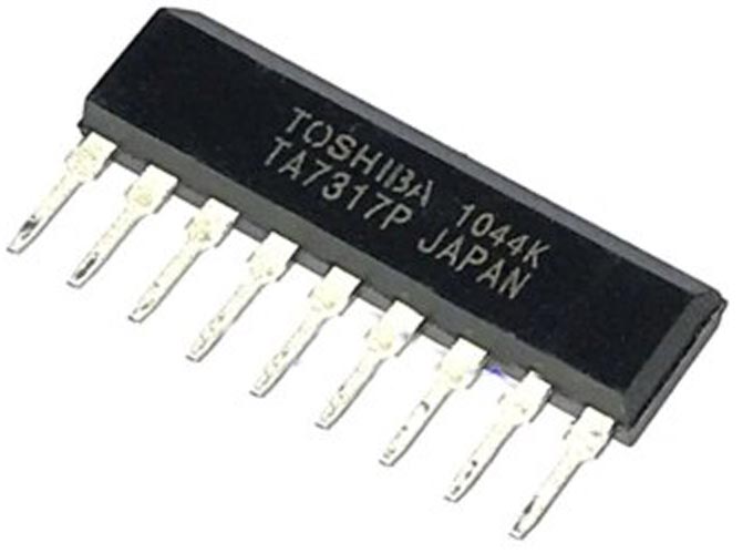
Feeling a bit nostalgic right now, thinking back to another classic IC, Toshiba’s fabled TA7317P (Figure 3). Designed for OCL power amplifier protection, TA7317P integrates functions like overcurrent detection, muting control, DC offset monitoring, and a relay driver to safeguard loudspeakers.
 |
|
| Figure 3. | TA7317P is designed for protecting power amplifiers. |
On another note, most audio power amplifiers incorporate dedicated circuitry to monitor current flow through the power transistors, ensuring it remains within the devices’ specified safe operating area (SOA).
Similarly, most muting control circuits delay connecting the loudspeaker when the amplifier powers on and immediately disconnect it upon power-off. In other words, these muting control circuits keep the loudspeakers disconnected until the amplifier stabilizes and swiftly disconnect them when power is cut off to prevent any turn-off noise the amplifier might generate.
Feature-rich ICs like the UPC1237 help conserve PCB space, reduce project costs, and enhance overall reliability. Despite their versatility, they never truly received a modern successor. Why is that?
To me, these ICs were very much a product of their era – back when analog audio systems were built in a more modular fashion. As digital technologies and integrated designs gained dominance, the need for dedicated analog protection circuits gradually faded. While they still have a loyal following in the DIY and vintage repair communities, that’s a relatively niche space.
Sure, equivalents like the NTE7100 or spin-off modules are still available, particularly in DIY audio circles. But a true evolution of the concept? That just never really materialized.
As a closing thought, here is the blueprint of a pretty simple analog front-end tailored for detecting audio offset to safeguard loudspeakers (Figure 4). I know there are similar circuits out there, but I just felt like doing my own thing.
 |
|
| Figure 4. | The analog front-end is designed to detect audio offset and safeguard loudspeakers. |
At its core, it operated simply: When a positive or negative DC voltage appears at the output of either or both audio channels, the respective bipolar capacitor starts charging through its series resistor. Once the voltage across the capacitor hits the threshold voltage (VF = 1.2 V as specified for the depicted photocoupler), the corresponding photocoupler is triggered.
There is no reason not to use much more complex circuits. The circuit idea shown here is rather adequate for the purpose. However, note that the scheme demands suitably rated parts to work in real life. So, do not take it as gospel; make this design your own.