So I came up with an idea of Cannon DSLR remote control. They are relatively cheap to buy on ebay, or other local online auction sites like allegro.pl here in Poland. But I wanted to build something by my self. As a complete amateur I wanted to make something small, and simple, thus DIY IR remote control for my camera was born.
http://www.doc-diy.net/photo/rc-1_hacked/
http://www.doc-diy.net/photo/eos_ir_remote/
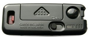
Canon RC-1
The protocol was reverse engineered by some smart people over the internet, so all I needed to do was to design the PCB, solder the stuff together, write a program and flash it.
My design is based on Atmel AVR ATtiny2313A which in my opinion is a little too powerful, but first tests with ATtiny13 revealed some issues with internal oscillator. The timing of the clock signal is crucial when generating a carrier wave. Carrier should have 32.6kHz frequency for the best results. Deviations from this frequency has significant impact on IR operational range. Without an oscilloscope I was unable calibrate internal oscillator correctly, thus I’ve chosen chip with an external one (in fact the clock frequency was the most difficult issue I’ve got and I spent most of the time dealing with it). After soldering 4MHz quartz into place, at first I set it up for divide by 8 prescaler operation thus giving me 0.5MHz clock signal, but it also failed. I really don’t know why, but it seems, that prescaler is somehow unstalble, or has some sort of overhead (I’m an amateur after all. If someone could explain it, I would be grateful). Finally after setting the chip to operate at full speed (prescaler turned down) I was able to trigger the shutter, but range of operation was still small (circa 3m / 10ft).
Schematic Diagram
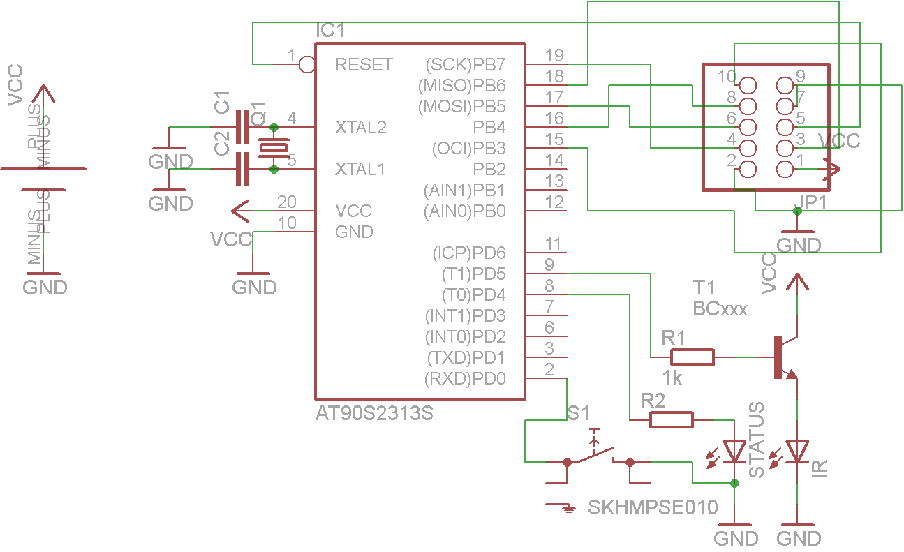
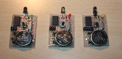
I’ve chosen not to drive my IR led directly from AVR pins (like guy in aforementioned links did), but rather use a transistor used as a switch. I assume in that way I’m able to drive bigger current for the IR diode making it to produce stronger flashes. Next to the IR diode you can see a status diode, which indicates to the user, that device is sending a signal. Also I wanted it to be fully reprogrammable thus the connector on the board is present.
The last thing I did was the power down mode. Circuit, when turned on draws ~5mA even, when idling, so I presume the CR2032 battery would not last for long. For prolonging battery life I turn the AVR into power down mode after 3 seconds, and I wake it up via ping change interrupt when button is pressed. AVR in power down mode draws no current at all according to my multimeter (which simply is not precise enough to detect it), but according to the AVR specs it should take about 0.1uA.
Total cost was something about $5-7, with AVR and casing being the most expensive parts.
Below you can find a link to archive with all the necessary files to duplicate my design. Archive include Eagle files (both PCB and schematic), avr-gcc source files with CMake scripts and ATtiny2131a binary). The code was developed in Eclipse.
Downloads
Project files - download