Part 1 - Schematic and Firmware
Improving the emulator
In the previous emulator schematic no inductance value has been defined.To improve the carrier reception - and therefore the reading distance -, the inductance and the capacitance should be tuned to resonate at the carrier frequency (125 KHz in this case).
Using the value of the parasite capacitor (around 30 pF) and a frequency of 125 KHz, we can calculate the value of the tuned inductance with the formula
![]()
The result is 54.04 mH.
However, the parasite capacitor value is an approximation. The real value differs from one device to other. It can even change due to external parameters (temperature, power voltage, clock frequency, etc). Using only the parasite capacitor makes almost impossible to tune correctly the LC circuit.
Adding an external capacitor in parallel to the coil makes much easier the tunning process. The capacitor should be at least 1 nF, so the variations on the parasite capacitance does not bias the tunning too much.
But a tuned antenna is not the only factor to take into account in order to improve the reading range.
Working at 125 KHz (wavelength of 2400 meters) means that, given the short reading range, the electromagnetic field created by the RFID reader can be considered as an alternating magnetical field. A large antenna will receive more magnetic flux than a small one, and a higher voltage will be induced in its terminals.
A manufactured axial inductor - like the one used in the video - has physically a small area and will not pickup too much carrier. The reading range will be very short.
We can construct a better antenna. For example, a helicoidal coil can be constructed with a toiler paper cardboard and some wire. It is easier than you think! You can use a tool like this one to calculate the inductance of your handmade coil. Once you have calculated the inductace, don't forget to tune the antenna with its corresponding capacitor.
A 150 uH coil and a 10 nF capacitor are good values to start with.
For reference, the antenna used in the video up there is a 10mH axial inductor. There is no tunning capacitor (besides the parasite capacitance), so the reading range is very short. Neither the small size of the inductor helps. In fact, as you can see in the video, the emulator only works in some points of the reader. To be more precise... it only works in the places where the magnetic field is maximum.
Another improvement is to use a decoupling capacitor between Vcc and Vss for stability reasons. 100 nF is enough.
The schematic with the cited improvements:
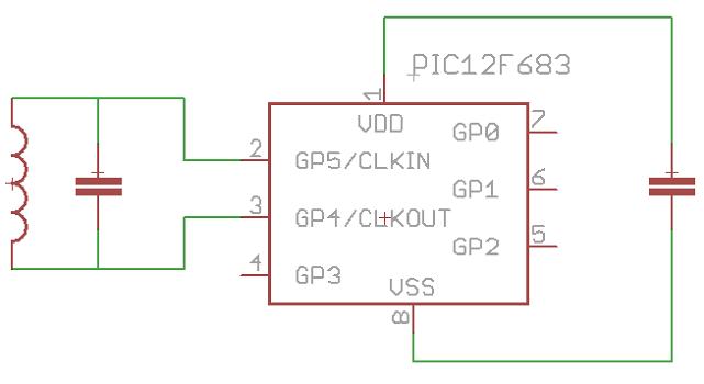
NOTES
The microcontroller used for this project is the PIC 12F683. However, any other PIC 12F (or even 16F) microcontroller is suitable for the emulator. The firmware should compile without any change.
Using a manufactured coil instead of homemade one can be tricky. Prepare yourself to do some try-outs.
Choose the biggest inductance possible because it will have a larger area. Be aware that some inductors can be covered with a conductive foil to isolate the coil from the EM noise.